DYNAMIC RADAR CRUISE CONTROL SYSTEM, Diagnostic DTC:C1A4A
| DTC Code | DTC Name |
|---|---|
| C1A4A | Skid Control Buzzer Circuit |
DESCRIPTION
Based on dynamic radar cruise control system operation, the driving support ECU assembly provides warnings to the driver by sounding the skid control buzzer assembly.
DTC C1A4A is stored when a malfunction is detected in the skid control buzzer assembly circuit.
| DTC No. | Detection Item | DTC Detection Condition | Trouble Area |
|---|---|---|---|
| C1A4A | Skid Control Buzzer Circuit | While the vehicle speed is 36 km/h (22 mph) or more and the dynamic radar cruise control system is operating, the driving support ECU assembly detects a malfunction in the skid control buzzer assembly circuit for approximately 0.4 seconds or more. |
|
WIRING DIAGRAM
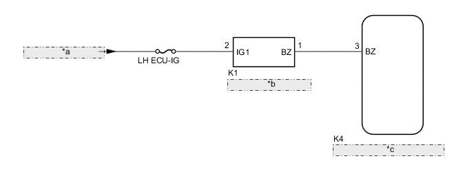
| *a | from LH-IG1 RLY1 Relay |
| *b | Skid Control Buzzer Assembly |
| *c | Driving Support ECU Assembly |
CAUTION / NOTICE / HINT
Note
-
Inspect the fuses for circuits related to this system before performing the following procedure.
-
When replacing the driving support ECU assembly, make sure to replace it with a new one. If a device which was installed to another vehicle is used, the information stored in the driving support ECU assembly will not match the information from the vehicle, and as a result, a DTC may be stored.
-
First check the CAN communication system by following How to Proceed with Troubleshooting. After checking that there are no malfunctions in the CAN communication system, proceed with troubleshooting.
-
for LHD:
-
for RHD:
PROCEDURE
-
CHECK FOR DTCs (PRE-CRASH SAFETY SYSTEM)
-
Check for DTCs of the pre-crash safety system.
Body Electrical > Pre-Crash 2 > Trouble CodesTech Tips
The dynamic radar cruise control system only stores DTC C1A4A when the vehicle speed reaches 36 km/h (22 mph), however the pre-crash safety system stores this DTC at any vehicle speed. If DTC C1A4A is stored by the pre-crash safety system, perform troubleshooting of the pre-crash safety system first.
Result Result Proceed to DTC C1A4A is not output A DTC C1A4A is output B
B 
GO TO PRE-CRASH SAFETY SYSTEM Click here
A 
-
-
CHECK FOR DTCs (RADAR CRUISE)
-
Clear the DTCs.
Powertrain > Radar Cruise > Clear DTCs -
Make sure that the DTC detection conditions are met.
Tech Tips
If the detection conditions are not met, the system cannot detect the malfunction.
-
Turn the engine switch on (IG).
-
Turn the dynamic radar cruise control system on using the cruise control main switch (ON/OFF button).
-
Drive the vehicle at 36 km/h (22 mph) or more for 1 second or more.
-
-
Check for DTCs.
Powertrain > Radar Cruise > Trouble CodesResult Result Proceed to DTC C1A4A is not output A DTC C1A4A is output B
A
USE SIMULATION METHOD TO CHECK Click here
B
-
-
INSPECT SKID CONTROL BUZZER ASSEMBLY (CONFIRM BUZZER OPERATION)
-
Turn the engine switch on (IG).
-
Check that the skid control buzzer assembly is sounds.
Result Result Proceed to The skid control buzzer assembly does not sound when the engine switch is on (IG). A The skid control buzzer assembly sounds continuously when the engine switch is on (IG). B
B 
CHECK HARNESS AND CONNECTOR (SKID CONTROL BUZZER - DRIVING SUPPORT ECU ASSEMBLY) Click here
A
-
-
CHECK HARNESS AND CONNECTOR (SKID CONTROL BUZZER ASSEMBLY - BATTERY)
-
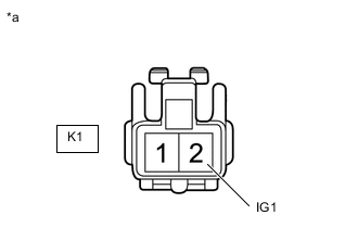
*a Front view of wire harness connector
(to Skid Control Buzzer Assembly)
Disconnect the skid control buzzer assembly connector.
-
Measure the voltage according to the value(s) in the table below.
Standard Voltage Tester Connection Switch Condition Specified Condition K1-2 (IG1) - Body ground Engine switch on (IG) 11 to 14 V K1-2 (IG1) - Body ground Engine switch off Below 1 V Result Proceed to OK NG
NG
REPAIR OR REPLACE HARNESS OR CONNECTOR
OK
-
-
CHECK HARNESS AND CONNECTOR (SKID CONTROL BUZZER ASSEMBLY - DRIVING SUPPORT ECU ASSEMBLY)
-
Disconnect the K1 skid control buzzer assembly connector.
-
Disconnect the K4 driving support ECU assembly connector.
-
Measure the resistance according to the value(s) in the table below.
Standard Resistance Tester Connection Condition Specified Condition K1-1 (BZ) - K4-3 (BZ) Always Below 1 Ω K1-1 (BZ) or K4-3 (BZ) - Body ground Always 10 kΩ or higher Result Proceed to OK NG
NG
REPAIR OR REPLACE HARNESS OR CONNECTOR
OK
-
-
INSPECT SKID CONTROL BUZZER ASSEMBLY
-
Remove the skid control buzzer.
-
Inspect the skid control buzzer.
Result Proceed to OK NG
OK
REPLACE DRIVING SUPPORT ECU ASSEMBLY Click here
NG
REPLACE SKID CONTROL BUZZER ASSEMBLY Click here
-
-
CHECK HARNESS AND CONNECTOR (SKID CONTROL BUZZER - DRIVING SUPPORT ECU ASSEMBLY)
-
Disconnect the K1 skid control buzzer connector.
-
Disconnect the K4 driving support ECU assembly connector.
-
Measure the resistance according to the value(s) in the table below.
Standard Resistance Tester Connection Condition Specified Condition K1-1 (BZ) - K4-3 (BZ) Always Below 1 Ω K1-1 (BZ) or K4-3 (BZ) - Body ground Always 10 kΩ or higher Result Proceed to OK NG
OK
REPLACE DRIVING SUPPORT ECU ASSEMBLY Click here
NG
REPAIR OR REPLACE HARNESS OR CONNECTOR
-