ENGINE OIL COOLER(for Air Cooled Type) INSTALLATION
PROCEDURE
-
PRECAUTION
Note
-
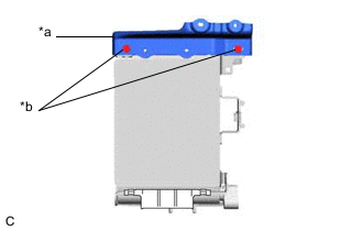
*a Upper Engine Oil Cooler Bracket *b Do not loosen If the bolts of the upper engine oil cooler bracket are loosened, the oil cooler assembly may move out of position and interfere with the front bumper assembly. Do not loosen the bolts of the upper engine oil cooler bracket.
-
If the bolts of the upper engine oil cooler bracket have been loosened, adjust the position of the oil cooler assembly.
-
When the oil cooler assembly (for air cooled type) has been removed/installed or the oil cooler hose sub-assembly has been disconnected/reconnected, check the engine oil level after warming up the engine oil to between 100°C (212°F) and 120°C (248°F) to open the thermostat between the engine and oil cooler assembly (for air cooled type).
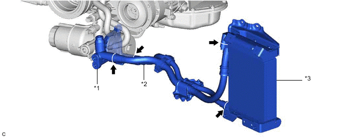
*1 Thermostat (Thermostat Housing Assembly) *2 Oil Cooler Hose Sub-assembly *3 Oil Cooler Assembly (for Air Cooled Type) - -
Tech Tips
Enter the following menus: Powertrain / Engine / Data List / Engine Oil Temperature Sensor.
Powertrain > Engine > Data ListTester Display Engine Oil Temperature Sensor -
-
INSTALL OIL COOLER ASSEMBLY (When Adjustment is Necessary)
Tech Tips
Perform this procedure only when the bolts of the upper engine oil cooler bracket have been loosened.
-
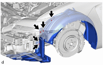
Remove the 5 screws and disconnect the front fender liner LH.
-
Install the lower engine oil cooler bracket to the oil cooler assembly with the 2 clips.
-
Install the outlet engine oil cooler air duct to the oil cooler assembly with the 2 bolts.
- Torque:
- 4.9 N*m { 50 kgf*cm, 43 in.*lbf }
-
Apply a small amount of engine oil to 3 new O-rings and install them to the oil cooler hose sub-assembly.
Note
Do not damage the O-rings.
-
Connect the oil cooler hose sub-assembly to the oil cooler assembly with the 3 bolts.
- Torque:
- 10 N*m { 102 kgf*cm, 7 ft.*lbf }
-
Engage the guide and install the inlet engine oil cooler air duct to the oil cooler assembly with the 2 bolts.
- Torque:
- 8.0 N*m { 82 kgf*cm, 71 in.*lbf }
-
Temporarily install the oil cooler assembly to the vehicle body with the 6 nuts and 2 bolts.
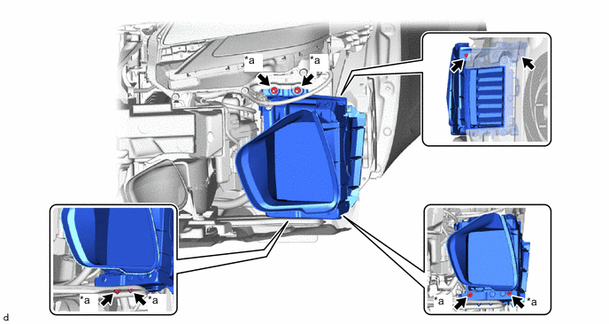
*a Nut - - -
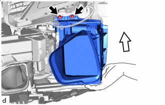

Support Fully tighten the 2 nuts.
- Torque:
- 8.0 N*m { 82 kgf*cm, 71 in.*lbf }
Tech Tips
Tighten the nuts while supporting the oil cooler assembly by hand as shown in the illustration.
-
Temporarily install the front bumper assembly.
-
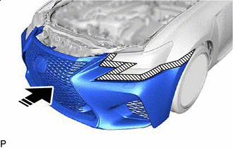

Install in this Direction Set the front bumper assembly on the vehicle as shown in the illustration.
-
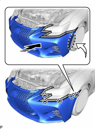
Install in this Direction (1) 
Install in this Direction (2) Engage the claws as shown in the illustration.
Tech Tips
Use the same procedure for the RH side and LH side.
-
-
Install the oil cooler assembly.
-
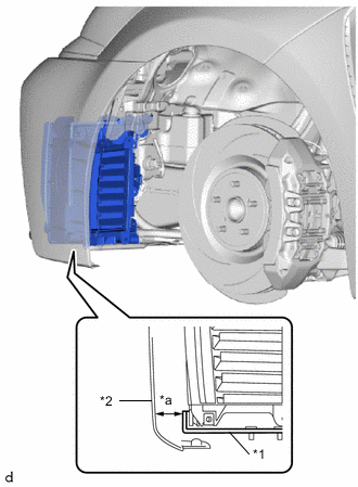
Fully tighten the 2 bolts (A).
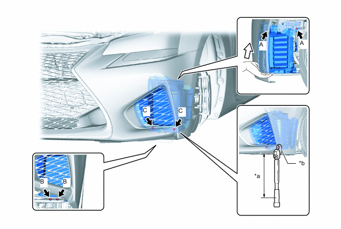
*a Torque Wrench Fulcrum Length *b 10 mm Union Nut Wrench Support - - - Torque:
- 4.9 N*m { 50 kgf*cm, 43 in.*lbf }
Tech Tips
Tighten the bolts while supporting the oil cooler assembly by hand as shown in the illustration.
-
Fully tighten the 2 nuts (B).
- Torque:
- 8.0 N*m { 82 kgf*cm, 71 in.*lbf }
-
Using a 10 mm union nut wrench, fully tighten the 2 nuts (C).
- Torque:
- Specified tightening torque
- 8.0 N*m { 82 kgf*cm, 71 in.*lbf }
Tech Tips
-
Calculate the torque wrench reading when changing the fulcrum length of the torque wrench.
-
When using a 10 mm union nut wrench (fulcrum length of 22 mm (0.866 in.)) + torque wrench (fulcrum length of 162 mm (6.38 in.)): 7.0 N*m (71 kgf*cm, 62 in.*lbf)
-
*1 Inlet Engine Oil Cooler Air Duct *2 No. 2 Radiator Grille Garnish Confirm that the clearance between the inlet engine oil cooler air duct and No. 2 radiator grille garnish is even.
-
-
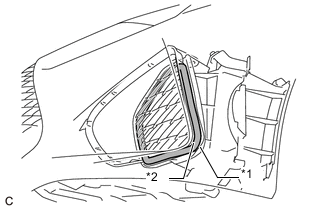
*1 Lower Engine Oil Cooler Bracket *2 Front Bumper Assembly *a Clearance Measure the clearance between the front bumper assembly and lower engine oil cooler bracket.
Standard Clearance 5.0 mm (0.197 in.) or more If the result is not as specified, perform adjustment again.
-
Remove the front bumper assembly.
-
Engage the clamp to connect the wire harness to the inlet engine oil cooler air duct.
-
Connect the front fender liner LH with the 5 screws.
-
Connect the outlet engine oil cooler air duct to the front fender liner LH with 2 new bolts and 3 clips.
- Torque:
- 8.0 N*m { 82 kgf*cm, 71 in.*lbf }
-
Connect the oil cooler hose sub-assembly to the No. 1 oil cooler bracket with the 2 nuts.
- Torque:
- 11 N*m { 112 kgf*cm, 8 ft.*lbf }
-
Apply a small amount of engine oil to 2 new O-rings and install them to the oil cooler hose sub-assembly.
Note
Do not damage the O-rings.
-
Connect the oil cooler hose sub-assembly to the oil thermostat housing assembly with the 2 bolts.
- Torque:
- 10 N*m { 102 kgf*cm, 7 ft.*lbf }
-
-
INSTALL OIL COOLER ASSEMBLY (When Adjustment is Not Necessary)
-
Install the lower engine oil cooler bracket to the oil cooler assembly with the 2 nuts and 2 clips.
- Torque:
- 8.0 N*m { 82 kgf*cm, 71 in.*lbf }
-
Install the outlet engine oil cooler air duct to the oil cooler assembly with the 2 bolts.
- Torque:
- 4.9 N*m { 50 kgf*cm, 43 in.*lbf }
-
Apply a small amount of engine oil to 3 new O-rings and install them to the oil cooler hose sub-assembly.
Note
Do not damage the O-rings.
-
Connect the oil cooler hose sub-assembly to the oil cooler assembly with the 3 bolts.
- Torque:
- 10 N*m { 102 kgf*cm, 7 ft.*lbf }
-
Install the oil cooler assembly with outlet engine oil cooler air duct to the vehicle body with the 4 nuts.
- Torque:
- 8.0 N*m { 82 kgf*cm, 71 in.*lbf }
-
Connect the outlet engine oil cooler air duct to the front fender liner LH with 2 new bolts and 3 clips.
- Torque:
- 8.0 N*m { 82 kgf*cm, 71 in.*lbf }
-
Connect the oil cooler hose sub-assembly to the No. 1 oil cooler bracket with the 2 nuts.
- Torque:
- 11 N*m { 112 kgf*cm, 8 ft.*lbf }
-
Apply a small amount of engine oil to 2 new O-rings and install them to the oil cooler hose sub-assembly.
Note
Do not damage the O-rings.
-
Connect the oil cooler hose sub-assembly to the oil thermostat housing assembly with the 2 bolts.
- Torque:
- 10 N*m { 102 kgf*cm, 7 ft.*lbf }
-
-
INSTALL INLET ENGINE OIL COOLER AIR DUCT (When Adjustment is Not Necessary)
-
Engage the guide and install the inlet engine oil cooler air duct to the oil cooler assembly with outlet engine oil cooler air duct with the 2 bolts.
- Torque:
- 8.0 N*m { 82 kgf*cm, 71 in.*lbf }
-
Engage the clamp to connect the wire harness to the inlet engine oil cooler air duct.
-
-
INSTALL FRONT BUMPER ASSEMBLY
-
ADD ENGINE OIL
-
CHECK ENGINE OIL LEVEL
-
INSPECT FOR ENGINE OIL LEAK
-
INSTALL NO. 1 ENGINE UNDER COVER ASSEMBLY
-
INSTALL FRONT WHEEL LH