OIL PUMP INSTALLATION

CAUTION / NOTICE / HINT
Note
When the oil cooler assembly (for air cooled type) has been removed/installed or the oil cooler hose sub-assembly has been disconnected/reconnected, check the engine oil level after warming up the engine oil to between 100°C (212°F) and 120°C (248°F) to open the thermostat between the engine and oil cooler assembly (for air cooled type).
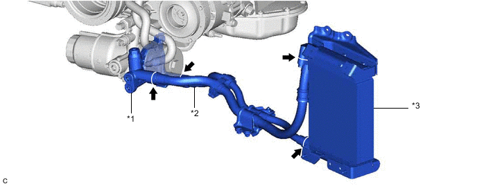
| *1 | Thermostat (Thermostat Housing Assembly) | *2 | Oil Cooler Hose Sub-assembly |
| *3 | Oil Cooler Assembly (for Air Cooled Type) | - | - |
Tech Tips
Enter the following menus: Powertrain / Engine / Data List / Engine Oil Temperature Sensor.
Powertrain > Engine > Data List
| Tester Display |
|---|
| Engine Oil Temperature Sensor |
PROCEDURE
-
INSTALL SCAVENGING PUMP ASSEMBLY
-
INSTALL NO. 3 OIL PIPE
-
INSTALL NO. 2 OIL PIPE
-
INSTALL NO. 1 OIL PIPE
-
INSTALL INLET WATER PIPE
-
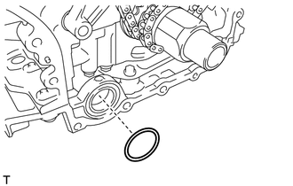
INSTALL TIMING GEAR CASE OR TIMING CHAIN CASE OIL SEAL
-
Apply MP grease to the lip of a new timing chain case or timing chain case oil seal.
-
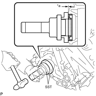
*a Standard Depth Using SST and a hammer, tap in the timing chain case or timing chain case oil seal until its surface is flush with the timing chain cover assembly edge.
- SST
- 09506-35010
Standard Depth -0.5 to 0.5 mm (-0.0197 to 0.0197 in.) (From the edge of the timing chain cover assembly) Note
-
Keep the lip free from foreign matter.
-
Do not tap in the timing chain case or timing chain case oil seal at an angle.
-
Do not tap in the oil seal excessively.
-
-
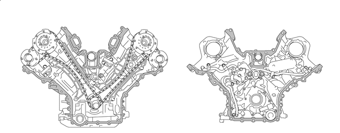
INSTALL TIMING CHAIN COVER ASSEMBLY
-
Remove any old packing remaining on the sealing surfaces before applying seal packing.
-
Clean the contact surfaces of the timing chain cover assembly, cylinder head sub-assembly, cylinder head LH and cylinder block sub-assembly and confirm that there is no oil, moisture or other foreign matter on the surfaces.

Area to be Cleaned and Degreased - - -
Install a new oil pump gasket.
-
Install a new O-ring.
-
Apply seal packing in a continuous line to the timing chain cover assembly as shown in the illustration.
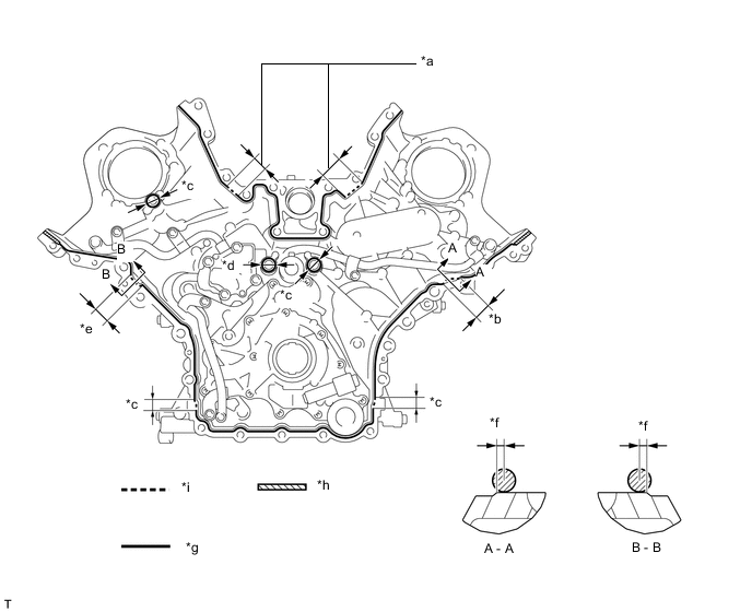
*a 20 mm (0.787 in.) *b 26 mm (1.02 in.) *c 16 mm (0.630 in.) *d 18 mm (0.709 in.) *e 23 mm (0.906 in.) *f 0.5 mm (0.0197 in.) *g Continuous Line Area *h Dashed Line Area *i Diagonal Line Area - - Seal Packing Toyota Genuine Seal Packing Black, Three Bond 1207B or equivalent Seal Packing Application Chart Area Seal Packing Diameter Application Position from Inside Edge of Cover Continuous Line Area 2.5 to 3.5 mm (0.0984 to 0.138 in.) 2.5 mm (0.0984 in.) Dashed Line Area 6.4 mm (0.252 in.) or more 0.5 mm (0.0197 in.) Diagonal Line Area 2.5 to 3.5 mm (0.0984 to 0.138 in.) 5.5 mm (0.217 in.) Note
-
If there is oil on the contact surfaces, wipe them with an oil-free cloth before applying seal packing.
-
Install the timing chain cover assembly within 3 minutes and tighten the bolts within 10 minutes of applying seal packing.
-
Do not add engine oil for at least 2 hours after installing the timing chain cover assembly.
-
Do not start the engine for at least 2 hours after installing the timing chain cover assembly.
-
-
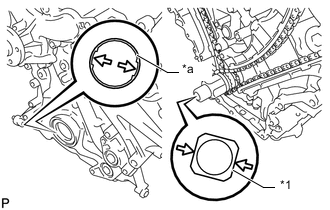
*1 Crankshaft *a Oil Pump Drive Rotor Spline Align the oil pump drive rotor spline and the crankshaft as shown in the illustration, and install the timing chain cover assembly.
-
*a Nut Temporarily install the timing chain cover assembly with the 30 bolts and nut.
Bolt Length: Item Length Thread Diameter Bolt (A) 25 mm (0.984 in.) 8 mm (0.315 in.) Bolt (B) 55 mm (2.17 in.) 8 mm (0.315 in.) Bolt (C) 70 mm (2.76 in.) 8 mm (0.315 in.) Bolt (D) 35 mm (1.38 in.) 10 mm (0.394 in.) Bolt (E) 80 mm (3.15 in.) 10 mm (0.394 in.) Bolt (F) 80 mm (3.15 in.) 10 mm (0.394 in.) Bolt (G) 80 mm (3.15 in.) 8 mm (0.315 in.) Note
Make sure that there is no oil on the bolt threads.
-
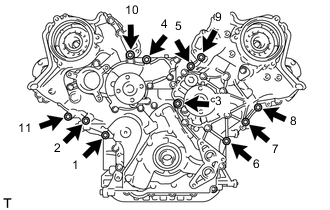
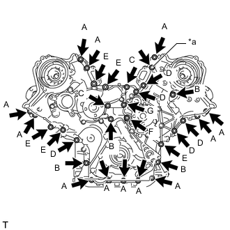
Tighten the 11 bolts in several steps in the order shown in the illustration.
- Torque:
- 47 N*m { 479 kgf*cm, 35 ft.*lbf }
-
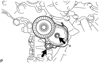
*a Hexagon Bolt Temporarily install the V-ribbed belt tensioner assembly with the bolt and hexagon bolt.
-
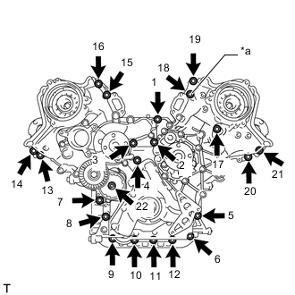
*a Nut Tighten the 21 bolts and nut in several steps in the order shown in the illustration.
- Torque:
- 23 N*m { 235 kgf*cm, 17 ft.*lbf }
-
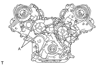
If the seal packing has seeped out at the areas (A) shown in the illustration, wipe it off.
-
-
INSTALL CAMSHAFT TIMING CONTROL MOTOR WITH EDU ASSEMBLY RH
-
INSTALL CAMSHAFT TIMING CONTROL MOTOR WITH EDU ASSEMBLY LH
-
INSTALL V-RIBBED BELT TENSIONER ASSEMBLY
-
INSTALL SPARK PLUG TUBE GASKET
-
INSTALL CYLINDER HEAD COVER SUB-ASSEMBLY LH
-
INSTALL CYLINDER HEAD COVER SUB-ASSEMBLY
-
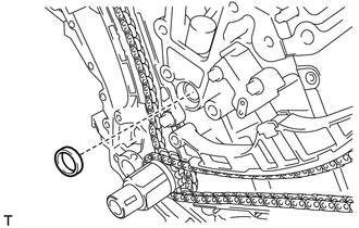
INSTALL CRANKSHAFT TIMING GEAR KEY
-
INSTALL CRANKSHAFT PULLEY
-
INSTALL OIL FILTER BRACKET SUB-ASSEMBLY
-
Install 2 new gaskets to the oil filter bracket sub-assembly.
-
Install the oil filter bracket sub-assembly with the 2 bolts and 2 nuts.
- Torque:
- 21 N*m { 214 kgf*cm, 15 ft.*lbf }
-
Install the oil filter bracket stay with the 2 bolts.
- Torque:
- 21 N*m { 214 kgf*cm, 15 ft.*lbf }
-
-
INSTALL FRONT WATER BY-PASS JOINT
-
INSTALL NO. 3 V-BANK COVER BRACKET SUB-ASSEMBLY
-
INSTALL NO. 4 V-BANK COVER BRACKET SUB-ASSEMBLY
-
INSTALL IGNITION COIL ASSEMBLY
-
INSTALL NO. 2 WATER BY-PASS PIPE SUB-ASSEMBLY
-
INSTALL WATER INLET HOUSING
-
INSTALL WATER PUMP PULLEY
-
INSTALL OIL PUMP DRIVE SHAFT PULLEY
-
INSTALL NO. 2 IDLER PULLEY SUB-ASSEMBLY
-
INSTALL GENERATOR ASSEMBLY
-
INSTALL COMPRESSOR WITH PULLEY ASSEMBLY
-
CONNECT SUCTION HOSE
-
CONNECT NO. 1 COOLER REFRIGERANT DISCHARGE HOSE
-
INSTALL FRONT STABILIZER BAR
-
INSTALL FRONT NO. 1 STABILIZER BRACKET LH
-
INSTALL FRONT NO. 1 STABILIZER BRACKET RH
Tech Tips
Use the same procedure as for the LH side.
-
INSTALL REAR ENGINE UNDER COVER LH
-
INSTALL REAR ENGINE UNDER COVER RH
Tech Tips
Use the same procedure as for the LH side.
-
INSTALL FAN AND GENERATOR V BELT
-
INSTALL FUEL PUMP WITH SEAL SUB-ASSEMBLY (for Bank 1)
-
INSTALL FUEL PUMP WITH SEAL SUB-ASSEMBLY (for Bank 2)
-
INSTALL BATTERY TRAY
-
INSTALL POWER STEERING ECU ASSEMBLY
-
for LHD:
-
for RHD:
-
-
ENGAGE ENGINE WIRE
-
INSTALL ENGINE ROOM ECU COVER
-
CONNECT NO. 2 RADIATOR HOSE
-
CONNECT NO. 1 RADIATOR HOSE
-
INSTALL RADIATOR RESERVE TANK ASSEMBLY
-
INSTALL AIR CLEANER CASE SUB-ASSEMBLY
-
INSTALL AIR CLEANER FILTER ELEMENT SUB-ASSEMBLY
-
INSTALL AIR CLEANER CAP WITH AIR CLEANER HOSE
-
CONNECT VENTILATION HOSE
-
INSTALL INLET NO. 1 AIR CLEANER
-
CONNECT CABLE TO NEGATIVE BATTERY TERMINAL
Note
When disconnecting the cable, some systems need to be initialized after the cable is reconnected.
-
ADD ENGINE OIL
-
ADD ENGINE COOLANT
-
ADD AUTOMATIC TRANSMISSION FLUID
-
CHARGE AIR CONDITIONING SYSTEM WITH REFRIGERANT
-
for HFC-134a (R134a):
-
for HFO-1234yf (R1234yf):
-
-
WARM UP ENGINE
-
for HFC-134a (R134a):
-
for HFO-1234yf (R1234yf):
-
-
INSPECT FOR COOLANT LEAK
-
INSPECT FOR ENGINE OIL LEAK
-
INSPECT FOR FUEL LEAK
-
INSPECT FOR EXHAUST GAS LEAK
-
INSPECT FOR REFRIGERANT LEAK
-
for HFC-134a (R134a):
-
for HFO-1234yf (R1234yf):
-
-
CHECK ENGINE OIL LEVEL
-
PERFORM INITIALIZATION
-
INSTALL NO. 1 ENGINE UNDER COVER ASSEMBLY
-
INSTALL COOL AIR INTAKE DUCT SEAL
-
INSTALL V-BANK COVER SUB-ASSEMBLY