OIL PUMP REMOVAL

CAUTION / NOTICE / HINT
The necessary procedures (adjustment, calibration, initialization, or registration) that must be performed after parts are removed, installed, or replaced during the timing chain cover assembly removal/installation are shown below.
| Replacement Part or Procedure | Necessary Procedure | Effect/Inoperative when not Performed | Link |
|---|---|---|---|
| Disconnect cable from negative battery terminal | Memorize steering angle neutral point | Parking assist monitor system | |
| LKA/LDA system | |||
| Pre-crash safety system | |||
| Adaptive high beam system | |||
| Reset power trunk lid | Power trunk lid system | ||
| Removal and installation of a camshaft timing control motor with EDU assembly | Inspection After Repair |
|
|
Note
When the oil cooler assembly (for air cooled type) has been removed/installed or the oil cooler hose sub-assembly has been disconnected/reconnected, check the engine oil level after warming up the engine oil to between 100°C (212°F) and 120°C (248°F) to open the thermostat between the engine and oil cooler assembly (for air cooled type).
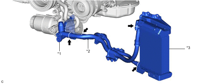
| *1 | Thermostat (Thermostat Housing Assembly) | *2 | Oil Cooler Hose Sub-assembly |
| *3 | Oil Cooler Assembly (for Air Cooled Type) | - | - |
Tech Tips
Enter the following menus: Powertrain / Engine / Data List / Engine Oil Temperature Sensor.
Powertrain > Engine > Data List
| Tester Display |
|---|
| Engine Oil Temperature Sensor |
PROCEDURE
-
REMOVE V-BANK COVER SUB-ASSEMBLY
-
REMOVE COOL AIR INTAKE DUCT SEAL
-
RECOVER REFRIGERANT FROM REFRIGERATION SYSTEM
-
for HFC-134a (R134a):
-
for HFO-1234yf (R1234yf):
-
-
DISCHARGE FUEL SYSTEM PRESSURE
-
DISCONNECT CABLE FROM NEGATIVE BATTERY TERMINAL
Note
When disconnecting the cable, some systems need to be initialized after the cable is reconnected.
-
REMOVE NO. 1 ENGINE UNDER COVER ASSEMBLY
-
DRAIN ENGINE OIL
-
DRAIN ENGINE COOLANT
-
DRAIN AUTOMATIC TRANSMISSION FLUID
-
REMOVE INLET NO. 1 AIR CLEANER
-
DISCONNECT VENTILATION HOSE
-
REMOVE AIR CLEANER CAP WITH AIR CLEANER HOSE
-
REMOVE AIR CLEANER FILTER ELEMENT SUB-ASSEMBLY
-
REMOVE AIR CLEANER CASE SUB-ASSEMBLY
-
REMOVE RADIATOR RESERVE TANK ASSEMBLY
-
DISCONNECT NO. 1 RADIATOR HOSE
-
DISCONNECT NO. 2 RADIATOR HOSE
-
REMOVE ENGINE ROOM ECU COVER
-
DISENGAGE ENGINE WIRE
-
REMOVE POWER STEERING ECU ASSEMBLY
-
for LHD:
-
for RHD:
-
-
REMOVE BATTERY TRAY
-
REMOVE FUEL PUMP WITH SEAL SUB-ASSEMBLY (for Bank 1)
-
REMOVE FUEL PUMP WITH SEAL SUB-ASSEMBLY (for Bank 2)
-
REMOVE FAN AND GENERATOR V BELT
-
REMOVE REAR ENGINE UNDER COVER LH
-
REMOVE REAR ENGINE UNDER COVER RH
Tech Tips
Use the same procedure as for the LH side.
-
REMOVE FRONT NO. 1 STABILIZER BRACKET LH
-
REMOVE FRONT NO. 1 STABILIZER BRACKET RH
Tech Tips
Use the same procedure as for the LH side.
-
REMOVE FRONT STABILIZER BAR
-
DISCONNECT NO. 1 COOLER REFRIGERANT DISCHARGE HOSE
-
DISCONNECT SUCTION HOSE
-
REMOVE COMPRESSOR WITH PULLEY ASSEMBLY
-
REMOVE GENERATOR ASSEMBLY
-
REMOVE NO. 2 IDLER PULLEY SUB-ASSEMBLY
-
REMOVE OIL PUMP DRIVE SHAFT PULLEY
-
REMOVE WATER PUMP PULLEY
-
REMOVE WATER INLET HOUSING
-
REMOVE NO. 2 WATER BY-PASS PIPE SUB-ASSEMBLY
-
REMOVE IGNITION COIL ASSEMBLY
-
REMOVE NO. 3 V-BANK COVER BRACKET SUB-ASSEMBLY
-
REMOVE NO. 4 V-BANK COVER BRACKET SUB-ASSEMBLY
-
REMOVE FRONT WATER BY-PASS JOINT
-
REMOVE OIL FILTER BRACKET SUB-ASSEMBLY
-
Remove the 2 bolts and oil filter bracket stay.
-
Remove the 2 bolts, 2 nuts and oil filter bracket sub-assembly.
-
Remove the 2 gaskets from the oil filter bracket sub-assembly.
-
-
REMOVE CRANKSHAFT PULLEY
-
REMOVE CRANKSHAFT TIMING GEAR KEY
-
REMOVE CYLINDER HEAD COVER SUB-ASSEMBLY LH
-
REMOVE CYLINDER HEAD COVER SUB-ASSEMBLY
-
REMOVE SPARK PLUG TUBE GASKET
-
REMOVE V-RIBBED BELT TENSIONER ASSEMBLY
-
REMOVE CAMSHAFT TIMING CONTROL MOTOR WITH EDU ASSEMBLY LH
-
REMOVE CAMSHAFT TIMING CONTROL MOTOR WITH EDU ASSEMBLY RH
-
REMOVE TIMING CHAIN COVER ASSEMBLY
-
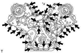
*a Nut Remove the 30 bolts and nut shown in the illustration.
-
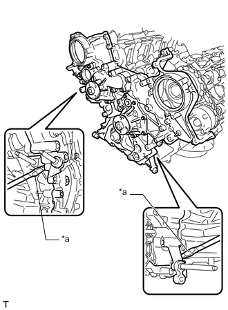
*a Protective Tape Remove the timing chain cover assembly by prying between the timing chain cover assembly and cylinder head sub-assembly and cylinder head LH or cylinder block sub-assembly with a screwdriver.
Note
Be careful not to damage the contact surfaces of the cylinder head sub-assembly, cylinder head LH or cylinder block sub-assembly and timing chain cover assembly.
Tech Tips
Tape the screwdriver tip before use.
-
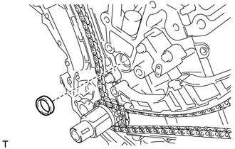
Remove the oil pump gasket from the cylinder block sub-assembly.
-
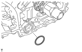
Remove the O-ring from the cylinder block sub-assembly.
-
-
REMOVE TIMING GEAR CASE OR TIMING CHAIN CASE OIL SEAL
-
Using a knife, cut through the lip of the timing gear case or timing chain case oil seal.
-
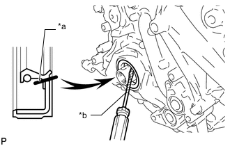
*a Cut Position *b Protective Tape Using a screwdriver, pry out the timing gear case or timing chain case oil seal.
Note
After the removal, check the crankshaft for damage.
If it is damaged, smooth the surface with 400-grit sandpaper.
Tech Tips
Tape the screwdriver tip before use.
-
-
REMOVE INLET WATER PIPE
-
REMOVE NO. 1 OIL PIPE
-
REMOVE NO. 2 OIL PIPE
-
REMOVE NO. 3 OIL PIPE
-
REMOVE SCAVENGING PUMP ASSEMBLY