INTAKE MANIFOLD REMOVAL
CAUTION / NOTICE / HINT
The necessary procedures (adjustment, calibration, initialization, or registration) that must be performed after parts are removed, installed, or replaced during the intake air surge tank assembly assembly removal/installation are shown below.
| Replacement Part or Procedure | Necessary Procedure | Effect/Inoperative when not Performed | Link |
|---|---|---|---|
| Disconnect cable from negative battery terminal | Memorize steering angle neutral point | Parking assist monitor system | |
| Lane departure alert system (w/ Steering Control) | |||
| Pre-crash safety system | |||
| Adaptive high beam system | |||
| Reset power trunk lid | Power trunk lid system |
PROCEDURE
-
PRECAUTION
Note
After turning the engine switch off, waiting time may be required before disconnecting the cable from the negative (-) battery terminal. Therefore, make sure to read the disconnecting the cable from the negative (-) battery terminal notices before proceeding with work.
-
DISCONNECT CABLE FROM NEGATIVE BATTERY TERMINAL
Note
When disconnecting the cable, some systems need to be initialized after the cable is reconnected.
-
REMOVE THROTTLE BODY WITH MOTOR ASSEMBLY
-
REMOVE PURGE VALVE (PURGE VSV)
-
REMOVE INJECTOR DRIVER
-
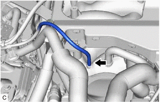
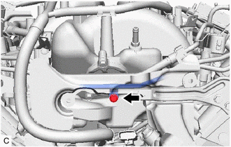
DISCONNECT UNION TO CHECK VALVE HOSE
-
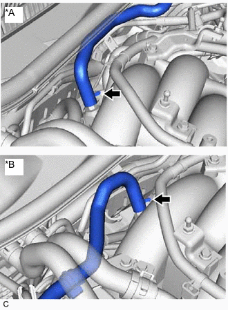
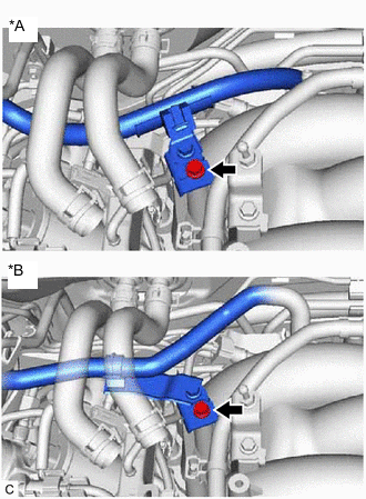
*A for LHD *B for RHD Slide the clip and disconnect the union to check valve hose from the intake air surge tank assembly.
-
-
REMOVE ENGINE ROOM ECU COVER
-
REMOVE NO. 1 ENGINE UNDER COVER ASSEMBLY
-
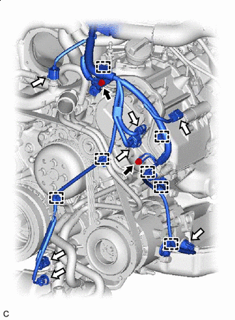
DISENGAGE ENGINE WIRE
-
for LHD:
-
Remove the 2 bolts and 4 nuts.
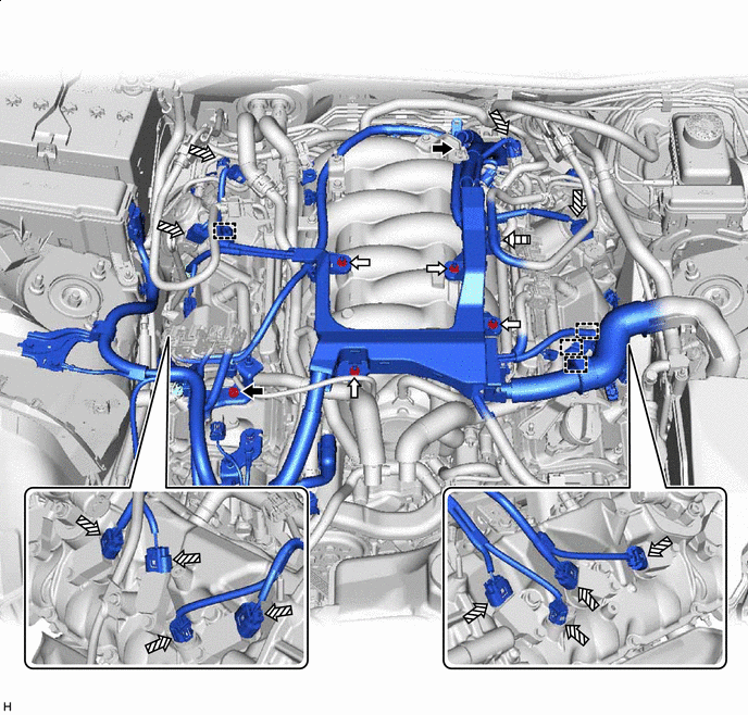

Bolt 
Nut 
Connector 
Fuel Tube Sub-assembly -
Disengage the 4 clamps.
-
Disconnect the 12 connectors.
-
Disengage the fuel tube sub-assembly from the engine wire.
-
-
for RHD:
-
Remove the 2 bolts and 4 nuts.
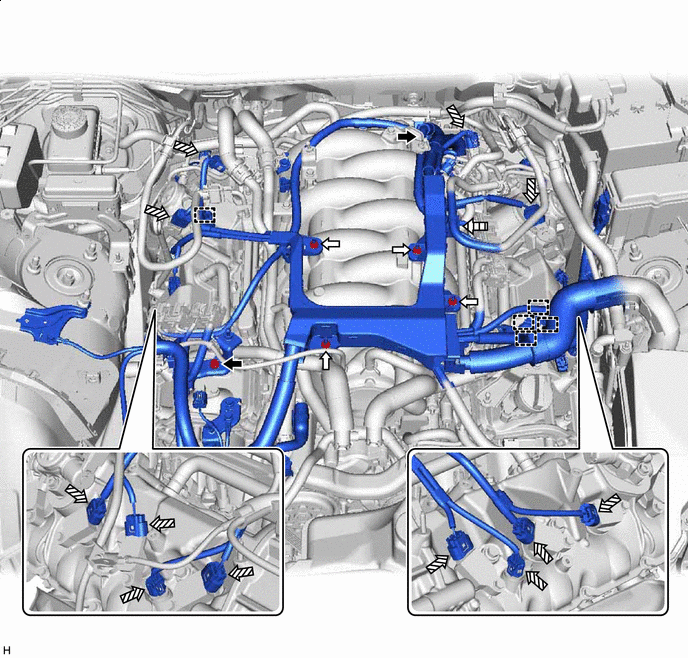
Bolt Nut Connector Fuel Tube Sub-assembly -
Disengage the 5 clamps.
-
Disconnect the 12 connectors.
-
Disengage the fuel tube sub-assembly from the engine wire.
-
-
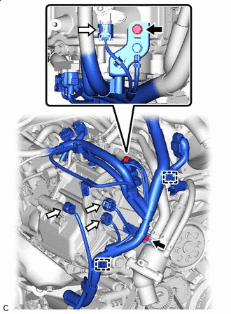
Bolt Connector Remove the 2 bolts.
-
Disengage the 2 clamps.
-
Disconnect the 4 connectors.
-
Bolt Connector Remove the 2 bolts.
-
Disengage the 7 clamps.
-
Disconnect the 7 connectors.
-
Disengage the claw and disconnect the engine wire harness.
-
Disconnect the engine wire harness connector.
-
Disengage the wire harness from the engine room ECU box.
-
-
DISCONNECT NO. 5 ENGINE WIRE
-
Disengage the 4 clamps and disconnect the No. 5 engine wire from the intake air surge tank assembly.
-
-
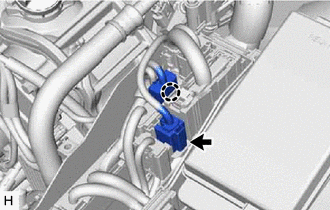
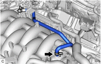
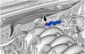
DISCONNECT VACUUM HOSE SUB-ASSEMBLY
-
Disconnect the vacuum hose sub-assembly from the intake air surge tank assembly.
-
-
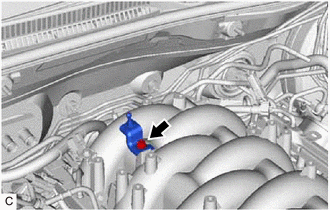
REMOVE FUEL VAPOR FEED HOSE
-
Slide the clip and remove the fuel vapor feed hose from the intake air surge tank assembly.
-
-
DISCONNECT VENTILATION HOSE
-
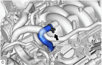
Slide the clip and disconnect the ventilation hose from the intake air surge tank assembly.
-
-
REMOVE INJECTOR DRIVER BRACKET
-
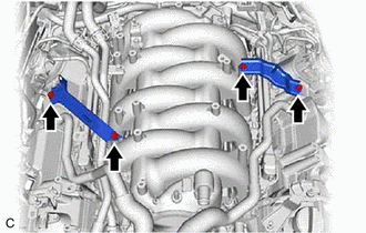
Remove the 4 bolts and 2 injector driver brackets from the intake air surge tank assembly, cylinder head cover sub-assembly LH and cylinder head cover sub-assembly.
-
-
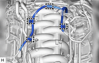
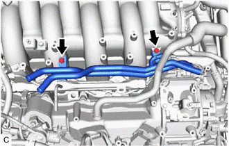
REMOVE WATER BY-PASS PIPE SUB-ASSEMBLY
-
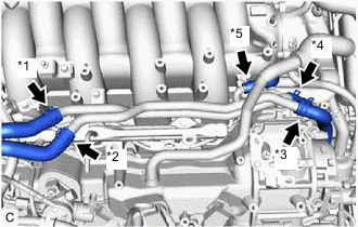
*1 Heater Water Inlet Hose *2 Heater Water Outlet Hose *3 No. 3 Water By-pass Hose *4 Water By-pass Hose *5 No. 5 Water By-pass Hose Slide the clip and disconnect the No. 3 water by-pass hose from the water by-pass pipe sub-assembly.
-
Slide the clip and disconnect the water by-pass hose from the water by-pass pipe sub-assembly.
-
Slide the clip and disconnect the No. 5 water by-pass hose from the water by-pass pipe sub-assembly.
-
Slide the clip and disconnect the heater water outlet hose from the water by-pass pipe sub-assembly.
-
Slide the clip and disconnect the heater water inlet hose from the water by-pass pipe sub-assembly.
-
Remove the 2 bolts and water by-pass pipe sub-assembly from the intake air surge tank assembly.
-
-
REMOVE FUEL TUBE SUB-ASSEMBLY
-
REMOVE NO. 2 FUEL DELIVERY PIPE SUB-ASSEMBLY
-
REMOVE FUEL DELIVERY PIPE SUB-ASSEMBLY
-
REMOVE NO. 1 DELIVERY PIPE SPACER
-
REMOVE INJECTOR VIBRATION INSULATOR
-
REMOVE PORT FUEL INJECTOR ASSEMBLY
-
REMOVE V-BANK COVER BRACKET SUB-ASSEMBLY
-
Remove the bolt and V-bank cover bracket sub-assembly from the intake air surge tank assembly.
-
-
REMOVE NO. 2 V-BANK COVER BRACKET SUB-ASSEMBLY
-
Remove the bolt and No. 2 V-bank cover bracket sub-assembly from the intake air surge tank assembly.
-
-
DISCONNECT NO. 1 FUEL PIPE SUB-ASSEMBLY
-
Remove the bolt and disconnect the No. 1 fuel pipe sub-assembly from the intake air surge tank assembly.
-
-
REMOVE INTAKE AIR SURGE TANK ASSEMBLY
-
*A for LHD *B for RHD Remove the bolt and disconnect the wire harness bracket from the intake air surge tank assembly.
-
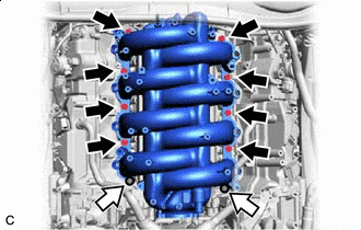
Bolt Nut Remove the 8 bolts and 2 nuts.
-
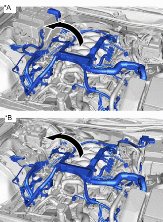
*A for LHD *B for RHD Pull the engine wire as shown in the illustration.
-
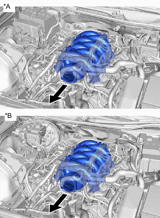
*A for LHD *B for RHD Remove the intake air surge tank assembly from the cylinder block sub-assembly.
-
Remove the 2 No. 1 intake manifold to head gaskets from the cylinder block sub-assembly.
-