FUEL SENDER GAUGE ASSEMBLY(w/ Canister Pump Module) REMOVAL

CAUTION / NOTICE / HINT
The necessary procedures (adjustment, calibration, initialization, or registration) that must be performed after parts are removed, installed, or replaced during the fuel sender gauge assembly or No. 2 fuel sender gauge assembly removal/installation are shown below.
| Replacement Part or Procedure | Necessary Procedure | Effect/Inoperative when not Performed | Link |
|---|---|---|---|
| Disconnect cable from negative battery terminal | Memorize steering angle neutral point | Parking assist monitor system | |
| LKA/LDA system | |||
| Pre-crash safety system | |||
| Adaptive high beam system | |||
| Reset power trunk lid | Power trunk lid system |
CAUTION:
-
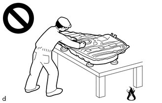
Never perform work on fuel system components near any possible ignition sources.
-
Vaporized fuel could ignite, resulting in a serious accident.
-
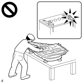
Do not perform work on fuel system components without first disconnecting the cable from the negative (-) battery terminal.
-
Sparks could cause vaporized fuel to ignite, resulting in a serious accident.
PROCEDURE
-
REMOVE FUEL SUCTION TUBE WITH PUMP AND GAUGE ASSEMBLY
-
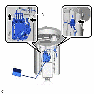
REMOVE FUEL SENDER GAUGE ASSEMBLY
-
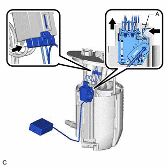
Disconnect the fuel sender gauge assembly connector.
-
Push the claw (A) of the fuel sender gauge assembly, and then pull up the fuel sender gauge assembly to remove it.
Note
-
Do not touch the resistance plate or contacts of the fuel sender gauge assembly.
-
Make sure that the fuel sender gauge assembly arm does not bend.
-
-
-
REMOVE REAR FLOOR SERVICE HOLE COVER
-
*a Protective Tape Using a clip remover with its tip wrapped with protective tape, remove the rear floor service hole cover and butyl tape.
-
Disconnect the No. 2 fuel sender gauge assembly connector.
-
-
REMOVE FUEL TANK VENT TUBE ASSEMBLY
-
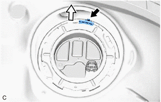

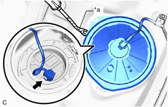
Front Side Release the lock and remove the No. 1 fuel tube clamp.
-
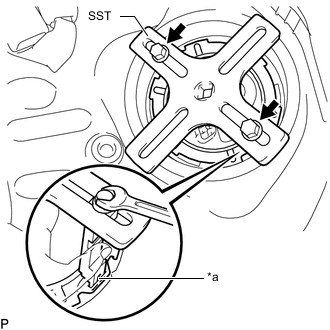
*a Insertion Point 
SST (Bolt) Set the 2 claws, 2 bolts and plate of SST on the fuel pump gauge retainer.
- SST
- 09808-14031 ( 09808-01010, 09808-01020, 09808-01030, 09808-01090 )
- 09808-01071
Tech Tips
Securely insert the ends of SST (claw) into the insertion points in the fuel pump gauge retainer.
-
While firmly pressing SST (claw) into the insertion points in the fuel pump gauge retainer, tighten SST (bolt).
-
Attach the handle of SST.
-
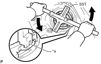
*a Insertion Point Check once more that the tip of SST is securely inserted into the insertion area of the fuel pump gauge retainer as shown in the illustration.
-
Lightly press down on SST to prevent it from separating from the fuel pump gauge retainer. While pressing down on SST, rotate SST (handle) slowly to loosen the fuel pump gauge retainer.
Note
-
Do not use any tools other than specified as this may result in damage to the fuel pump gauge retainer or the fuel tank assembly.
-
Do not press down on SST excessively as this may make the fuel pump gauge retainer hard to rotate, and may damage components.
-
Make sure to rotate SST (handle) horizontally. If it is rotated at an angle, SST may come off.
-
Do not spin SST too fast or use an impact wrench as this may result in damage to components.
-
If SST comes off of the fuel pump gauge retainer, loosen SST (bolt) and reinstall SST.
-
-
While pressing down on the fuel tank vent tube assembly, remove the fuel pump gauge retainer.
-
Disconnect the fuel return vent tube sub-assembly and remove the fuel tank vent tube assembly from the fuel tank assembly.
Note
-
Make sure that the No. 2 fuel sender gauge assembly arm does not bend.
-
Do not damage the fuel return vent tube sub-assembly.
-
When disconnecting the fuel tube connector, do not excessively pull on the fuel return vent tube sub-assembly.
-
-
Remove the fuel suction tube set gasket from the fuel tank assembly.
-
-
REMOVE NO. 2 FUEL SENDER GAUGE ASSEMBLY
-
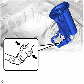
Disconnect the No. 2 fuel sender gauge assembly connector.
-
Push the claw (A) of the No. 2 fuel sender gauge assembly, and then pull up the No. 2 fuel sender gauge assembly to remove it.
Note
-
Do not touch the resistance plate or contacts of the No. 2 fuel sender gauge assembly.
-
Make sure that the No. 2 fuel sender gauge assembly arm does not bend.
-
-