AUTOMATIC TRANSMISSION ASSEMBLY REMOVAL

CAUTION / NOTICE / HINT
The necessary procedures (adjustment, calibration, initialization, or registration) that must be performed after parts are removed, installed, or replaced during the automatic transmission assembly removal/installation are shown below.
| Replacement Part or Procedure | Necessary Procedure | Effect/Inoperative when not Performed | Link |
|---|---|---|---|
| Disconnect cable from negative battery terminal | Memorize steering angle neutral point | Parking assist monitor system | |
| Lane departure alert system (w/ Steering Control) | |||
| Pre-crash safety system | |||
| Adaptive high beam system | |||
| Reset power trunk lid | Power trunk lid system | ||
| Replacement of automatic transmission assembly |
|
|
|
| Front wheel alignment adjustment |
|
|
-
*: New automatic transmission's compensation code.
CAUTION:
-
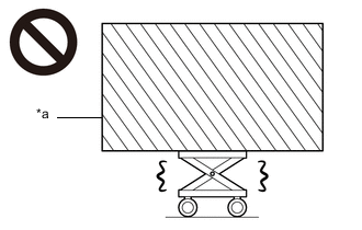
*a Heavy object exceeding the capacity of the engine lifter Because the weight of the engine assembly with automatic transmission assembly is extremely heavy, make sure to follow the work procedures described in the repair manual.
-
If work is not performed according to the procedures described in the repair manual, there is a danger that the engine lifter could drop and components could fall down.
PROCEDURE
-
REMOVE STARTER ASSEMBLY
-
REMOVE ENGINE MOUNTING DAMPER
-
REMOVE NO. 2 EXHAUST MANIFOLD HEAT INSULATOR
-
REMOVE EXHAUST MANIFOLD SUB-ASSEMBLY LH (TWC: Front Catalyst)
-
REMOVE EXHAUST MANIFOLD TO HEAD GASKET (for Bank 1)
-
REMOVE NO. 1 EXHAUST PIPE SUPPORT BRACKET SUB-ASSEMBLY
-
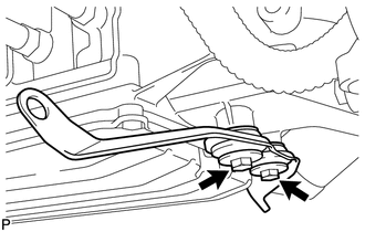
Remove the 2 bolts and No. 1 exhaust pipe support bracket sub-assembly from the automatic transmission assembly.
-
-
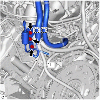
REMOVE OIL COOLER TUBE
-
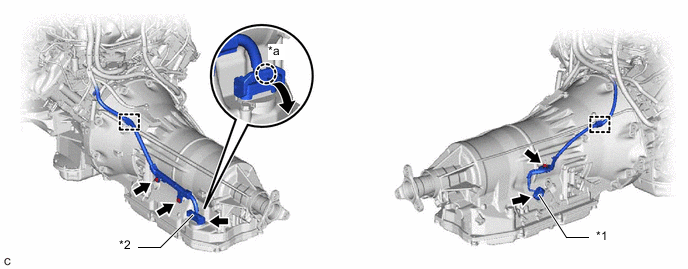
Slide the 2 clips and disconnect the 2 oil cooler hoses from the automatic transmission assembly.
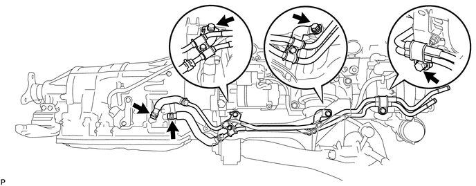
Tech Tips
Use a container to catch any ATF which flows out of the 2 oil cooler hoses.
-
Remove the 3 bolts, No. 2 flexible hose clamp and oil cooler tube from the engine assembly.
-
-
REMOVE DRIVE PLATE AND TORQUE CONVERTER ASSEMBLY SETTING BOLT
-
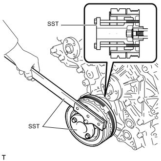
Using SST, hold the crankshaft pulley.
- SST
- 09213-38010
- 09330-00021
-
Remove the 6 drive plate and torque converter assembly setting bolts.
Tech Tips
There will be one black colored bolt.
-
-
REMOVE REAR ENGINE MOUNTING MEMBER
-
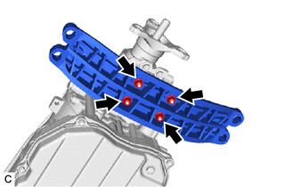
Remove the 4 nuts and rear engine mounting member from the rear engine mounting insulator assembly.
-
-
REMOVE REAR ENGINE MOUNTING INSULATOR ASSEMBLY
-
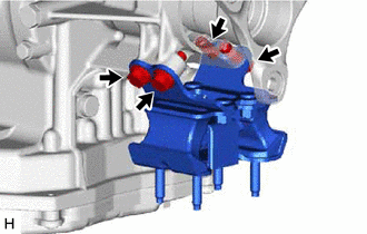
Remove the 4 bolts and rear engine mounting insulator assembly from the automatic transmission assembly.
-
-
REMOVE FLOOR SHIFT GEAR SHIFTING ROD SUB-ASSEMBLY
-
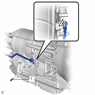
*1 Pin Remove the clip.
-
Remove the pin and floor shift gear shifting rod sub-assembly from the transmission control shaft lever RH.
-
-
DISCONNECT WIRE HARNESS
-
Disconnect the park/neutral position switch connector.
*1 Park/Neutral Position Switch Connector *2 Transmission Wire Connector *a Claw - - -
Disconnect the transmission wire connector.
Tech Tips
Disengage the claw, pull down the lever, and then disconnect the transmission wire connector.
-
Disengage the 2 clamps.
-
Remove the nut and 2 bolts.
-
Disconnect the wire harness from the automatic transmission assembly.
-
-
REMOVE AUTOMATIC TRANSMISSION ASSEMBLY
-
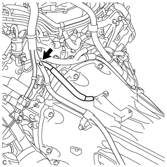
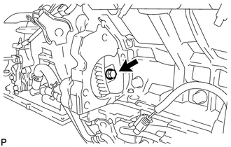
Disconnect the breather plug hose from the transmission breather assembly.
-
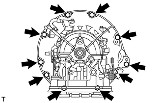
Remove the 10 bolts and automatic transmission assembly from the engine assembly.
Note
To prevent damage to the 2 knock pins, do not pry between the automatic transmission assembly and engine assembly.
-
-
REMOVE TORQUE CONVERTER ASSEMBLY
-
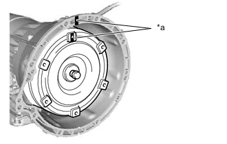
*a Matchmark Put matchmarks on the automatic transmission case sub-assembly and torque converter assembly.
-
Remove the torque converter assembly from the automatic transmission assembly.
Note
Remove the torque converter assembly from the input shaft horizontally.
-
-
REMOVE TRANSMISSION BREATHER ASSEMBLY
-
*1 Ground Wire Remove the bolt to disconnect the ground wire from transmission breather assembly.
-
Disengage the 2 clamps to disconnect the wire harness from transmission breather assembly.
-
Remove the 2 bolts and transmission breather assembly from the engine assembly.
-
-
INSPECT TORQUE CONVERTER ASSEMBLY
-
INSPECT DRIVE PLATE AND RING GEAR SUB-ASSEMBLY