AIR COOLED OIL COOLER INSTALLATION
PROCEDURE
-
PRECAUTION
Note
-
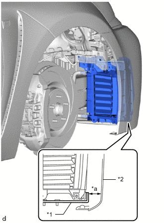
If the bolts of the upper transmission oil cooler bracket are loosened, the oil cooler assembly may move out of position and interfere with the front bumper assembly. Do not loosen the bolts of the upper transmission oil cooler bracket.
-
If the bolts of the upper transmission oil cooler bracket have been loosened, adjust the position of the oil cooler assembly.
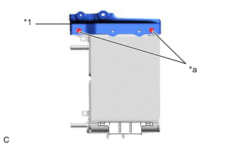
*1 Upper Transmission Oil Cooler Bracket *a Do not loosen -
-
INSTALL OIL COOLER ASSEMBLY (When Adjustment is Necessary)
Tech Tips
Perform this procedure only when the bolts of the upper transmission oil cooler bracket have been loosened.
-
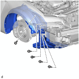
Remove the 5 screws and disconnect the front fender liner RH.
-
Install the transmission oil cooler bracket to the oil cooler assembly with the 2 clips.
-
Install the outlet transmission oil cooler air duct to the oil cooler assembly with the 2 bolts.
- Torque:
- 4.9 N*m { 50 kgf*cm, 43 in.*lbf }
-
Engage the clamp to install the hose clamp to the No. 5 transmission oil cooler hose.
-
Install the No. 5 transmission oil cooler hose to the oil cooler assembly and slide the clip to secure it.
-
Engage the clamp to install the hose clamp to the No. 6 transmission oil cooler hose.
-
Install the No. 6 transmission oil cooler hose to the oil cooler assembly and slide the clip to secure it.
-
Engage the guide and install the transmission oil cooler air duct to the oil cooler assembly with the 2 bolts.
- Torque:
- 8.0 N*m { 82 kgf*cm, 71 in.*lbf }
-
Temporarily install the oil cooler assembly to the vehicle body with the 6 nuts and 2 bolts.
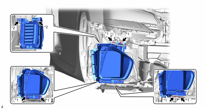
*1 Nut *2 Bolt -

Support Fully tighten the 2 nuts.
- Torque:
- 8.0 N*m { 82 kgf*cm, 71 in.*lbf }
Tech Tips
Tighten the nuts while supporting the oil cooler assembly by hand as shown in the illustration.
-
Temporarily install the front bumper assembly.
-
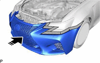

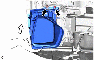
Install in this Direction Set the front bumper assembly on the vehicle as shown in the illustration.
-
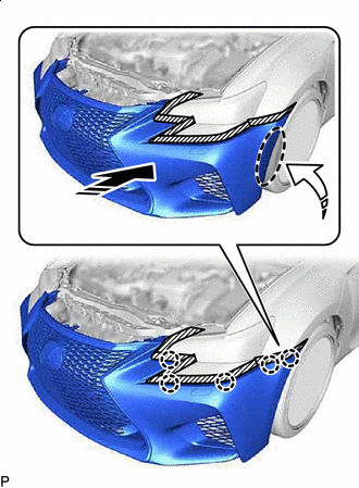
Install in this Direction (1) 
Install in this Direction (2) Engage the claws as shown in the illustation.
Tech Tips
Use the same procedure for the RH side and LH side.
-
-
Install the oil cooler assembly
-
Fully tighten the 2 bolts (A).
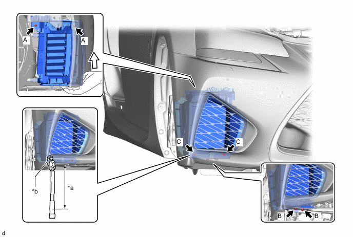
*a Torque Wrench Fulcrum Length *b 10 mm Union Nut Wrench Support - - - Torque:
- 4.9 N*m { 50 kgf*cm, 43 in.*lbf }
Tech Tips
Tighten the bolts while supporting the oil cooler assembly by hand as shown in the illustration.
-
Fully tighten the 2 nuts (B).
- Torque:
- 8.0 N*m { 82 kgf*cm, 71 in.*lbf }
-
Using a 10 mm union nut wrench, fully tighten the 2 nuts (C).
- Torque:
- Specified tightening torque
- 8.0 N*m { 82 kgf*cm, 71 in.*lbf }
Tech Tips
-
Calculate the torque wrench reading when changing the fulcrum length of the torque wrench.
-
When using a 10 mm union nut wrench (fulcrum length of 22 mm (0.866 in.)) + torque wrench (fulcrum length of 162 mm (6.38 in.)): 7.0 N*m (71 kgf*cm, 62 in.*lbf)
-
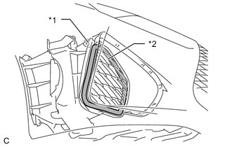
*1 Transmission Oil Cooler Air Duct *2 Radiator Grille Garnish Confirm that the clearance between the transmission oil cooler air duct and radiator grille garnish is even.
-
-
*1 Transmission Oil Cooler Bracket *2 Front Bumper Assembly *a Clearance Measure the clearance between the front bumper assembly and transmission oil cooler bracket.
Standard Clearance 5.0 mm (0.197 in.) or more If the result is not as specified, perform adjustment again.
-
Remove the front bumper assembly.
-
Engage the clamp to connect the wire harness to the transmission oil cooler air duct.
-
Connect the front fender liner RH with the 5 screws.
-
Connect the outlet transmission oil cooler air duct to the front fender liner RH with 2 new bolts and the 3 clips.
- Torque:
- 8.0 N*m { 82 kgf*cm, 71 in.*lbf }
-
Connect the No. 6 transmission oil cooler hose to the oil cooler tube sub-assembly and slide the clip to secure it.
-
Engage the clamp to connect the No. 6 transmission oil cooler hose to the cool air intake duct.
-
Connect the No. 5 transmission oil cooler hose to the oil cooler tube sub-assembly and slide the clip to secure it.
-
Engage the clamp to connect the No. 5 transmission oil cooler hose to the cool air intake duct.
-
-
INSTALL OIL COOLER ASSEMBLY (When Adjustment is Not Necessary)
-
Install the transmission oil cooler bracket to the oil cooler assembly with the 2 nuts and 2 clips.
- Torque:
- 8.0 N*m { 82 kgf*cm, 71 in.*lbf }
-
Install the outlet transmission oil cooler air duct to the oil cooler assembly with the 2 bolts.
- Torque:
- 4.9 N*m { 50 kgf*cm, 43 in.*lbf }
-
Engage the clamp to install the hose clamp to the No. 5 transmission oil cooler hose.
-
Install the No. 5 transmission oil cooler hose to the oil cooler assembly and slide the clip to secure it.
-
Engage the clamp to install the hose clamp to the No. 6 transmission oil cooler hose.
-
Install the No. 6 transmission oil cooler hose to the oil cooler assembly and slide the clip to secure it.
-
Install the oil cooler assembly with outlet transmission oil cooler air duct to the vehicle body with the 4 nuts.
- Torque:
- 8.0 N*m { 82 kgf*cm, 71 in.*lbf }
-
Connect the outlet transmission oil cooler air duct to the front fender liner RH with 2 new bolts and the 3 clips.
- Torque:
- 8.0 N*m { 82 kgf*cm, 71 in.*lbf }
-
Connect the No. 6 transmission oil cooler hose to the oil cooler tube sub-assembly and slide the clip to secure it.
-
Engage the clamp to connect the No. 6 transmission oil cooler hose to the cool air intake duct.
-
Connect the No. 5 transmission oil cooler hose to the oil cooler tube sub-assembly and slide the clip to secure it.
-
Engage the clamp to connect the No. 5 transmission oil cooler hose to the cool air intake duct.
-
-
INSTALL TRANSMISSION OIL COOLER AIR DUCT (When Adjustment is Not Necessary)
-
Engage the guide and install the transmission oil cooler air duct to the oil cooler assembly with the 2 bolts.
- Torque:
- 8.0 N*m { 82 kgf*cm, 71 in.*lbf }
-
Engage the clamp to connect the wire harness to the transmission oil cooler air duct.
-
-
INSTALL FRONT BUMPER ASSEMBLY
-
ADD AUTOMATIC TRANSMISSION FLUID
-
INSTALL NO. 2 ENGINE UNDER COVER
-
INSTALL FRONT SUSPENSION MEMBER BRACE SUB-ASSEMBLY
-
INSTALL NO. 1 ENGINE UNDER COVER ASSEMBLY
-
INSTALL FRONT WHEEL RH