LIGHTING SYSTEM Footwell Light Circuit
DESCRIPTION
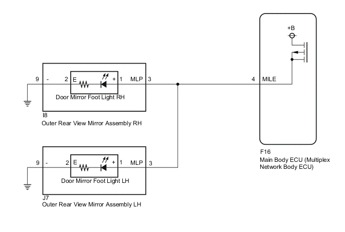
The main body ECU (multiplex network body ECU) controls the door mirror foot lights.
WIRING DIAGRAM
PROCEDURE
-
PERFORM ACTIVE TEST USING GTS
-
Connect the GTS to the DLC3.
-
Turn the power switch on (IG).
-
Turn the GTS on.
-
Enter the following menus: Body Electrical / Main Body / Active Test.
-
Perform the Active Test according to the display on the GTS.
Body Electrical > Main Body > Active TestTester Display Measurement Item Control Range Diagnostic Note Side Mirror Foot Light Door mirror foot lights ON/OFF -
Body Electrical > Main Body > Active TestTester Display Side Mirror Foot Light OK Door mirror foot lights illuminate. Result Result Proceed to OK A NG (for LH Side) B NG (for RH Side) C
A 
PROCEED TO NEXT SUSPECTED AREA SHOWN IN PROBLEM SYMPTOMS TABLE Click here
C 
CHECK OUTER REAR VIEW MIRROR ASSEMBLY RH (POWER SOURCE) Click here
B 
-
-
CHECK OUTER REAR VIEW MIRROR ASSEMBLY LH (POWER SOURCE)
-
Disconnect the J7 outer rear view mirror assembly LH connector.
-
Measure the voltage according to the value(s) in the table below.
Standard Voltage Tester Connection Condition Specified Condition J7-3 (MLP) - Body ground Illumination conditions of door mirror foot light met* 11 to 14 V
-
*: Refer to System Description for the illumination conditions of the door mirror foot light.
Result Proceed to OK NG -
NG
REPAIR OR REPLACE HARNESS OR CONNECTOR
OK
-
-
INSPECT DOOR MIRROR FOOT LIGHT LH
-
Remove the door mirror foot light LH.
-
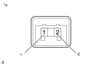
*a Component without harness connected
(Door Mirror Foot Light LH)
Check the door mirror foot light LH illumination.
-
Apply battery voltage between the terminals of the door mirror foot light LH and check the illumination condition of the door mirror foot light LH.
OK Condition Specified Condition Battery positive (+) → Terminal 1 (+)
Battery negative (-) → Terminal 2 (E)
Illuminates
Result Proceed to OK NG -
NG
REPLACE DOOR MIRROR FOOT LIGHT LH Click here
OK
-
-
CHECK HARNESS AND CONNECTOR (OUTER REAR VIEW MIRROR ASSEMBLY LH - BODY GROUND)
-
Disconnect the J7 outer rear view mirror assembly LH connector.
-
Measure the resistance according to the value(s) in the table below.
Standard Resistance Tester Connection Condition Specified Condition J7-9 (-) - Body ground Always Below 1 Ω Result Proceed to OK NG
OK
REPLACE OUTER REAR VIEW MIRROR ASSEMBLY LH Click here
NG
REPAIR OR REPLACE HARNESS OR CONNECTOR
-
-
CHECK OUTER REAR VIEW MIRROR ASSEMBLY RH (POWER SOURCE)
-
Disconnect the I8 outer rear view mirror assembly RH connector.
-
Measure the resistance according to the value(s) in the table below.
Standard Voltage Tester Connection Condition Specified Condition I8-3 (MLP) - Body ground Illumination conditions of door mirror foot light met* 11 to 14 V
-
*: Refer to System Description for the illumination conditions of the door mirror foot light.
Result Proceed to OK NG -
NG
REPAIR OR REPLACE HARNESS OR CONNECTOR
OK
-
-
INSPECT DOOR MIRROR FOOT LIGHT RH
-
Remove the door mirror foot light RH.
-
*a Component without harness connected
(Door Mirror Foot Light RH)
Check the door mirror foot light RH illumination.
-
Apply battery voltage between the terminals of the door mirror foot light RH and check the illumination condition of the door mirror foot light RH.
OK Condition Specified Condition Battery positive (+) → Terminal 1 (+)
Battery negative (-) → Terminal 2 (E)
Illuminates
Result Proceed to OK NG -
NG
REPLACE DOOR MIRROR FOOT LIGHT RH Click here
OK
-
-
CHECK HARNESS AND CONNECTOR (OUTER REAR VIEW MIRROR ASSEMBLY RH - BODY GROUND)
-
Disconnect the I8 outer rear view mirror assembly RH connector.
-
Measure the resistance according to the value(s) in the table below.
Standard Resistance Tester Connection Condition Specified Condition I8-9 (-) - Body ground Always Below 1 Ω Result Proceed to OK NG
OK
REPLACE OUTER REAR VIEW MIRROR ASSEMBLY RH Click here
NG
REPAIR OR REPLACE HARNESS OR CONNECTOR
-