LIGHTING SYSTEM High Beam Headlight Circuit
DESCRIPTION
-
The headlight ECU sub-assemblies control the high beam headlights.
for LED Headlight:
-
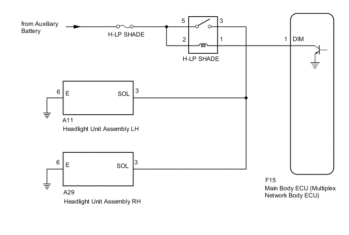
The main body ECU (multiplex network body ECU) controls the high beam headlights.
for Halogen Headlight:
WIRING DIAGRAM
-
for LED Headlight
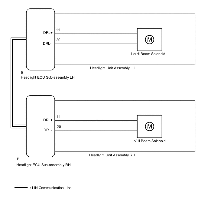
-
for Halogen Headlight
CAUTION / NOTICE / HINT
Note
-
If the headlight ECU sub-assembly LH has been replaced, it is necessary to synchronize the vehicle information and initialize the headlight ECU sub-assembly LH.
for LED Headlight
-
Inspect the fuse for circuits related to this system before performing the following procedure.
-
Check the operation of the low beam headlights. If the low beam headlights do not operate normally, refer to Problem Symptoms Table.
-
Before replacing the main body ECU (multiplex network body ECU), refer to Service Bulletin.
for Halogen Headlight
PROCEDURE
-
SYSTEM CHECK
-
Check the vehicle specifications.
Result Result Proceed to for LED Headlight A for Halogen Headlight B
B 
PERFORM ACTIVE TEST USING GTS (HEAD LIGHT HI) Click here
A 
-
-
PERFORM ACTIVE TEST USING GTS (HEADLIGHT HIGH BEAM)
-
Connect the GTS to the DLC3.
-
Turn the power switch to on (IG).
-
Turn the GTS on.
-
Enter the following menus: Body Electrical / HL AutoLeveling / Active Test.
-
Perform the Active Test according to the display on the GTS.
Body Electrical > HL AutoLeveling > Active TestTester Display Measurement Item Control Range Diagnostic Note Headlight High Beam High beam headlights ON or OFF -
Body Electrical > HL AutoLeveling > Active TestTester Display Headlight High Beam Result Result Proceed to OK A NG (for LH Side) B NG (for RH Side) C
A 
PROCEED TO NEXT SUSPECTED AREA SHOWN IN PROBLEM SYMPTOMS TABLE Click here
C
REPLACE HEADLIGHT UNIT ASSEMBLY RH Click here
B
-
-
REPLACE HEADLIGHT UNIT ASSEMBLY LH
-
Replace the headlight unit assembly LH with a new or known good one.
-
Check that the high beam light LH operate normally.
OK High beam light LH operate normally. Result Proceed to OK NG
OK
END (HEADLIGHT UNIT ASSEMBLY LH WAS DEFECTIVE)
NG
REPLACE HEADLIGHT ECU SUB-ASSEMBLY LH Click here
-
-
REPLACE HEADLIGHT UNIT ASSEMBLY RH
-
Replace the headlight unit assembly RH with a new or known good one.
-
Check that the high beam light RH operate normally.
OK High beam light RH operate normally. Result Proceed to OK NG
OK
END (HEADLIGHT UNIT ASSEMBLY RH WAS DEFECTIVE)
NG
REPLACE HEADLIGHT ECU SUB-ASSEMBLY RH Click here
-
-
PERFORM ACTIVE TEST USING GTS (HEAD LIGHT HI)
-
Connect the GTS to the DLC3.
-
Turn the power switch to on (IG).
-
Turn the GTS on.
-
Enter the following menus: Body Electrical / Main Body / Active Test.
-
Check that the high beam headlights illuminate.
Body Electrical > Main Body > Active TestTester Display Measurement Item Control Range Diagnostic Note Head Light Hi High beam headlights ON or OFF -
Body Electrical > Main Body > Active TestTester Display Head Light Hi OK The high beam headlights illuminate. Result Proceed to OK NG
OK
PROCEED TO NEXT SUSPECTED AREA SHOWN IN PROBLEM SYMPTOMS TABLE Click here
NG
-
-
INSPECT H-LP SHADE RELAY
-
Remove the H-LP SHADE relay from the No. 1 engine room relay block.
-
Inspect the H-LP SHADE relay.
Result Proceed to OK NG
NG
REPLACE H-LP SHADE RELAY
OK
-
-
CHECK HARNESS AND CONNECTOR (H-LP SHADE RELAY - AUXILIARY BATTERY)
-
Measure the voltage according to the value(s) in the table below.
Standard Voltage Tester Connection Switch Condition Specified Condition Relay terminal 2- Body ground Power switch off 11 to 14 V Relay terminal 5- Body ground Power switch off 11 to 14 V Result Proceed to OK NG
NG
REPAIR OR REPLACE HARNESS OR CONNECTOR
OK
-
-
CHECK HARNESS AND CONNECTOR (H-LP SHADE RELAY - HEADLIGHT ASSEMBLY LH AND HEADLIGHT ASSEMBLY RH AND BODY GROUND)
-
Disconnect the A11 headlight assembly LH connector.
-
Disconnect the A29 headlight assembly RH connector.
-
Measure the resistance according to the value(s) in the table below.
Standard Resistance Tester Connection Condition Specified Condition Relay terminal 3 - A11-3 (SOL) Always Below 1 Ω Relay terminal 3 - A29-3 (SOL) Always Below 1 Ω A11-6 (E) - Body ground Always Below 1 Ω A29-6 (E) - Body ground Always Below 1 Ω Relay terminal 3 - Body ground Always 10 kΩ or higher Result Proceed to OK NG
NG
REPAIR OR REPLACE HARNESS OR CONNECTOR
OK
-
-
CHECK HARNESS AND CONNECTOR (H-LP SHADE RELAY - MAIN BODY ECU (MULTIPLEX NETWORK BODY ECU))
-
Disconnect the F15 main body ECU (Multiplex network body ECU) connector.
-
Measure the resistance according to the value(s) in the table below.
Standard Resistance Tester Connection Condition Specified Condition Relay terminal 1 - F15-1 (DIM) Always Below 1 Ω Relay terminal 1- Body ground Always 10 kΩ or higher Result Result Proceed to OK (for LHD) A OK (for RHD) B NG C
A
REPLACE MAIN BODY ECU (MULTIPLEX NETWORK BODY ECU) Click here
B
REPLACE MAIN BODY ECU (MULTIPLEX NETWORK BODY ECU) Click here
C
REPAIR OR REPLACE HARNESS OR CONNECTOR
-