WIPER AND WASHER SYSTEM Headlight Cleaner Motor and Relay Circuit
DESCRIPTION
-
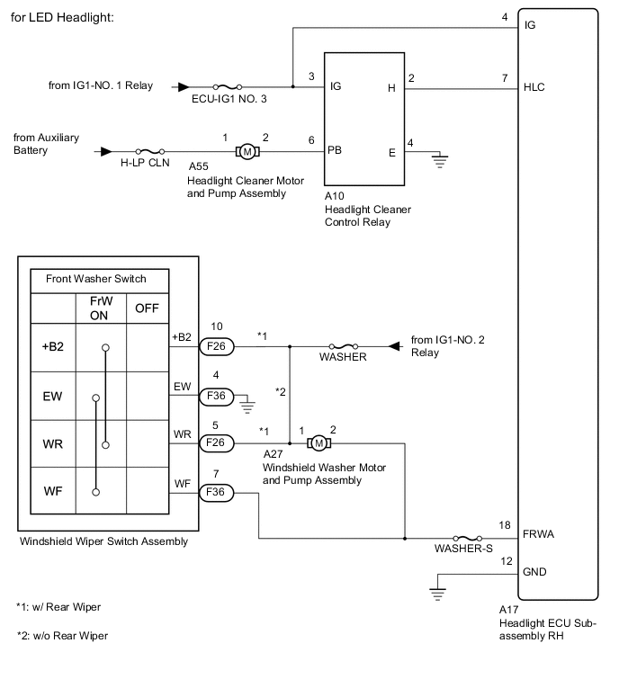
The headlight ECU sub-assembly RH controls the headlight cleaner motor and pump assembly.
for LED Headlight:
-
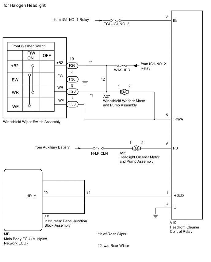
The headlight cleaner control relay controls the headlight cleaner motor and pump assembly.
for Halogen Headlight:
WIRING DIAGRAM
CAUTION / NOTICE / HINT
Note
-
First check that the front washer operates normally.
-
Inspect the fuses and relays for circuits related to this system before performing the following inspection procedure.
PROCEDURE
-
CHECK HEADLIGHT TYPE
-
Check the headlight type.
Result Result Proceed to for LED Headlight A for Halogen Headlight B
B 
CHECK HARNESS AND CONNECTOR (WINDSHIELD WIPER SWITCH ASSEMBLY - HEADLIGHT CLEANER CONTROL RELAY) Click here
A 
-
-
READ VALUE USING GTS
-
Read the Data List according to the display on the GTS.
Body Electrical > HL AutoLeveling > Data ListTester Display Measurement Item Range Normal Condition Diagnostic Note Front Window Washer Switch Washer switch condition ON/OFF ON: Windshield wiper switch assembly (front washer switch) on
OFF: Windshield wiper switch assembly (front washer switch) off
-
Body Electrical > HL AutoLeveling > Data ListTester Display Front Window Washer Switch OK On the GTS screen, ON or OFF is displayed accordingly. Result Proceed to OK NG
NG
CHECK HARNESS AND CONNECTOR (HEADLIGHT ECU SUB-ASSEMBLY RH - WINDSHIELD WIPER SWITCH ASSEMBLY) Click here
OK
-
-
INSPECT HEADLIGHT CLEANER CONTROL RELAY
-
Disconnect the A10 headlight cleaner control relay connector.
-
Inspect the headlight cleaner control relay.
Result Proceed to OK NG
NG 
REPLACE HEADLIGHT CLEANER CONTROL RELAY
OK
-
-
CHECK HARNESS AND CONNECTOR (HEADLIGHT CLEANER CONTROL RELAY - AUXILIARY BATTERY AND BODY GROUND)
-
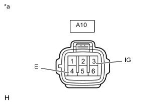
*a Front view of wire harness connector
(to Headlight Cleaner Control Relay)
Disconnect the headlight cleaner control relay connector.
-
Measure the voltage according to the value(s) in the table below.
Standard Voltage Tester Connection Switch Condition Specified Condition A10-3 (IG) - Body ground Power switch on (IG) 11 to 14 V -
Measure the resistance according to the value(s) in the table below.
Standard Resistance Tester Connection Switch Condition Specified Condition A10-4 (E) - Body ground Always Below 1 Ω Result Proceed to OK NG
NG
REPAIR OR REPLACE HARNESS OR CONNECTOR
OK
-
-
CHECK HARNESS AND CONNECTOR (HEADLIGHT CLEANER MOTOR AND PUMP ASSEMBLY CIRCUIT)
-
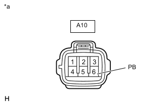
*a Front view of wire harness connector
(to Headlight Cleaner Control Relay)
Disconnect the headlight cleaner control relay connector.
-
Using a service wire, connect A10-6 (PB) and body ground.
Note
Do not forcibly insert the service wire into the terminals of the connector when connecting a service wire.
-
Check the headlight cleaner motor and pump assembly operate.
OK Headlight cleaner motor and pump assembly operate. Result Proceed to OK NG
NG
CHECK HARNESS AND CONNECTOR (HEADLIGHT CLEANER MOTOR AND PUMP ASSEMBLY - AUXILIXRY BATTERY) Click here
OK
-
-
CHECK HARNESS AND CONNECTOR (HEADLIGHT CLEANER CONTROL RELAY - HEADLIGHT ECU SUB-ASSEMBLY RH)
-
Disconnect the A10 headlight cleaner control relay connector.
-
Disconnect the A17 headlight ECU sub-assembly RH connector.
-
Measure the resistance according to the value(s) in the table below.
Standard Resistance Tester Connection Condition Specified Condition A10-2 (H) - A17-7 (HLC) Always Below 1 Ω A10-2 (H) or A17-7 (HLC) - Body ground Always 10 kΩ or higher Result Proceed to OK NG
OK
REPLACE HEADLIGHT ECU SUB-ASSEMBLY RH Click here
NG
REPAIR OR REPLACE HARNESS OR CONNECTOR
-
-
CHECK HARNESS AND CONNECTOR (HEADLIGHT ECU SUB-ASSEMBLY RH - WINDSHIELD WIPER SWITCH ASSEMBLY)
-
Disconnect the A17 headlight ECU sub-assembly RH connector.
-
Disconnect the F36 windshield wiper switch assembly connector.
-
Measure the resistance according to the value(s) in the table below.
Standard Resistance Tester Connection Condition Specified Condition A17-18 (FRWA) - F36-7 (WF) Always Below 1 Ω A17-18 (FRWA) or F36-7 (WF) - Body ground Always 10 kΩ or higher Result Proceed to OK NG
OK
REPLACE HEADLIGHT ECU SUB-ASSEMBLY RH Click here
NG
REPAIR OR REPLACE HARNESS OR CONNECTOR
-
-
CHECK HARNESS AND CONNECTOR (HEADLIGHT CLEANER MOTOR AND PUMP ASSEMBLY - AUXILIXRY BATTERY)
-

*a Front view of wire harness connector
(to Headlight Cleaner Motor and Pump Assembly)
Disconnect the headlight cleaner motor and pump assembly connector.
-
Measure the voltage according to the value(s) in the table below.
Standard Voltage Tester Connection Condition Specified Condition A55-1 - Body ground Power switch off 11 to 14 V Result Proceed to OK NG
NG
REPAIR OR REPLACE HARNESS OR CONNECTOR
OK
-
-
CHECK HARNESS AND CONNECTOR (HEADLIGHT CLEANER MOTOR AND PUMP ASSEMBLY - HEADLIGHT CLEANER CONTROL RELAY)
-
Disconnect the A55 headlight cleaner motor and pump assembly connector.
-
Disconnect the A10 headlight cleaner control relay connector.
-
Measure the resistance according to the value(s) in the table below.
Standard Resistance Tester Connection Condition Specified Condition A55-2 - A10-6 (PB) Always Below 1 Ω A55-2 or A10-6 (PB) - Body ground Always 10 kΩ or higher Result Proceed to OK NG
OK
REPLACE HEADLIGHT CLEANER MOTOR AND PUMP ASSEMBLY Click here
NG
REPAIR OR REPLACE HARNESS OR CONNECTOR
-
-
CHECK HARNESS AND CONNECTOR (WINDSHIELD WIPER SWITCH ASSEMBLY - HEADLIGHT CLEANER CONTROL RELAY)
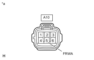
*a Front view of wire harness connector
(to Headlight Cleaner Control Relay)
-
Disconnect the headlight cleaner control relay connector.
-
Measure the voltage according to the value(s) in the table below.
Standard Voltage Tester Connection Condition Specified Condition A10-5 (FRWA) - Body ground Power switch on (IG), front washer switch off 11 to 14 V Power switch on (IG), front washer switch on Below 1 V Result Proceed to OK NG
NG
REPAIR OR REPLACE HARNESS OR CONNECTOR
OK
-
-
CHECK HARNESS AND CONNECTOR (HEADLIGHT CLEANER CONTROL RELAY - IG CIRCUIT AND BODY GROUND)
-

*a Front view of wire harness connector
(to Headlight Cleaner Control Relay)
Disconnect the headlight cleaner control relay connector.
-
Measure the voltage according to the value(s) in the table below.
Standard Voltage Tester Connection Condition Specified Condition A10-3 (IG) - Body ground Power switch on (IG) 11 to 14 V -
Measure the resistance according to the value(s) in the table below.
Standard Resistance Tester Connection Condition Specified Condition A10-4 (E) - Body ground Always Below 1 Ω Result Proceed to OK NG
NG
REPAIR OR REPLACE HARNESS OR CONNECTOR
OK
-
-
CHECK HARNESS AND CONNECTOR (HEADLIGHT CLEANER MOTOR AND PUMP ASSEMBLY CIRCUIT)
-

*a Front view of wire harness connector
(to Headlight Cleaner Control Relay)
Disconnect the headlight cleaner control relay connector.
-
Using a service wire, connect A10-6 (PB) and body ground.
Note
Do not forcibly insert the service wire into the terminals of the connector when connecting a service wire.
-
Check the headlight cleaner motor and pump assembly operate.
OK Headlight cleaner motor and pump assembly operate. Result Proceed to OK NG
NG
CHECK HARNESS AND CONNECTOR (HEADLIGHT CLEANER MOTOR AND PUMP ASSEMBLY - AUXILIARY BATTERY) Click here
OK
-
-
CHECK HARNESS AND CONNECTOR (INSTRUMENT PANEL JUNCTION BLOCK ASSEMBLY - HEADLIGHT CLEANER CONTROL RELAY)
-
Measure the voltage according to the value(s) in the table below.
Standard Voltage Tester Connection Condition Specified Condition 3F-31 - Body ground Light control switch in head position Below 1 V Light control switch off 4.2 V or higher Result Proceed to OK NG
OK
REPLACE HEADLIGHT CLEANER CONTROL RELAY
NG
-
-
CHECK HARNESS AND CONNECTOR (INSTRUMENT PANEL JUNCTION BLOCK ASSEMBLY - HEADLIGHT CLEANER CONTROL RELAY)
-
Disconnect the 3F instrument panel junction block assembly connector.
-
Disconnect the A10 headlight cleaner control relay connector.
-
Measure the resistance according to the value(s) in the table below.
Standard Resistance Tester Connection Condition Specified Condition 3F-31 - A10-1 (HDLO) Always Below 1 Ω 3F-31 or A10-1 (HDLO) - Body ground Always 10 kΩ or higher Result Proceed to OK NG
NG
REPAIR OR REPLACE HARNESS OR CONNECTOR
OK
-
-
INSPECT INSTRUMENT PANEL JUNCTION BLOCK ASSEMBLY
-
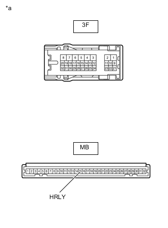
*a Component without harness connected
(Instrument Panel Junction Block Assembly)
Remove the instrument panel junction block assembly.
-
Remove the main body ECU (multiplex network body ECU).
-
Measure the resistance according to the value(s) in the table below.
Standard Resistance Tester Connection Condition Specified Condition 3F-31 - MB-15 (HRLY) Always Below 1 Ω 3F-31 - Body ground Always 10 kΩ or higher Result Proceed to OK NG
NG
REPLACE INSTRUMENT PANEL JUNCTION BLOCK ASSEMBLY Click here
OK
-
-
REPLACE HEADLIGHT CLEANER CONTROL RELAY
-
Replace the headlight cleaner control relay assembly with a new or a known good one.
Result Result Proceed to The operation of the headlight cleaner returns to normal. OK The operation of the headlight cleaner does not return to normal. NG
OK
END (HEADLIGHT CLEANER CONTROL RELAY WAS DEFECTIVE)
NG
REPLACE MAIN BODY ECU (MULTIPLEX NETWORK BODY ECU) Click here
-
-
CHECK HARNESS AND CONNECTOR (HEADLIGHT CLEANER MOTOR AND PUMP ASSEMBLY - AUXILIARY BATTERY)
-
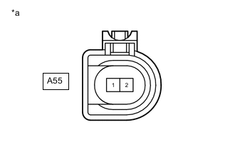
*a Front view of wire harness connector
(to Headlight Cleaner Motor and Pump Assembly)
Disconnect the headlight cleaner motor and pump assembly connector.
-
Measure the voltage according to the value(s) in the table below.
Standard Voltage Tester Connection Condition Specified Condition A55-1 - Body ground Always 11 to 14 V Result Proceed to OK NG
NG
REPAIR OR REPLACE HARNESS OR CONNECTOR
OK
-
-
CHECK HARNESS AND CONNECTOR (HEADLIGHT CLEANER MOTOR AND PUMP ASSEMBLY - HEADLIGHT CLEANER CONTROL RELAY)
-
Disconnect the A55 headlight cleaner motor and pump assembly connector.
-
Disconnect the A10 headlight cleaner control relay connector.
-
Measure the resistance according to the value(s) in the table below.
Standard Resistance Tester Connection Condition Specified Condition A55-2 - A10-6 (PB) Always Below 1 Ω A55-2 or A10-6 (PB) - Body ground Always 10 kΩ or higher Result Proceed to OK NG
OK
REPLACE HEADLIGHT CLEANER MOTOR AND PUMP ASSEMBLY Click here
NG
REPAIR OR REPLACE HARNESS OR CONNECTOR
-