FRONT DOOR DISASSEMBLY

Info Added 2017-10-06 ![]()
CAUTION / NOTICE / HINT
The necessary procedures (adjustment, calibration, initialization or registration) that must be performed after parts are removed and installed, or replaced during the front door removal/installation are shown below.
| Replaced Part or Performed Procedure | Necessary Procedure | Effect/Inoperative Function when Necessary Procedure not Performed | Link |
|---|---|---|---|
| Disconnect cable from negative auxiliary battery terminal | Memorize steering angle neutral point | Lane departure alert system (w/ Steering Control) | |
| Simple intelligent parking assist system*1 | |||
| Toyota parking assist-sensor system*1 | |||
| Pre-collision System | |||
| Initialize back door lock | Power door lock control system | ||
|
Initialize Power Window Control System |
|
*1: When performing learning using the GTS.
Tech Tips
-
Use the same procedure for the RH side and LH side.
-
The following procedure is for the LH side.
PROCEDURE
-
PRECAUTION
Note
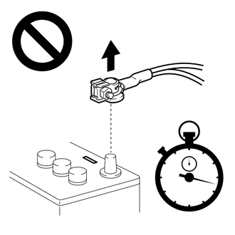
After turning the ignition switch off, waiting time may be required before disconnecting the cable from the negative (-) auxiliary battery terminal. Therefore, make sure to read the disconnecting the cable from the negative (-) auxiliary battery terminal notices before proceeding with work.
-
DISCONNECT CABLE FROM NEGATIVE AUXILIARY BATTERY TERMINAL
CAUTION:
Wait at least 90 seconds after disconnecting the cable from the negative (-) auxiliary battery terminal to disable the SRS system.
Note
When disconnecting the cable, some systems need to be initialized after the cable is reconnected.
-
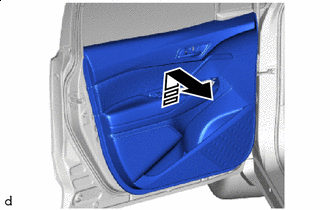
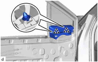
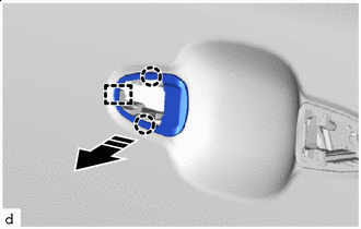
REMOVE FRONT DOOR INSIDE HANDLE BEZEL PLUG
-
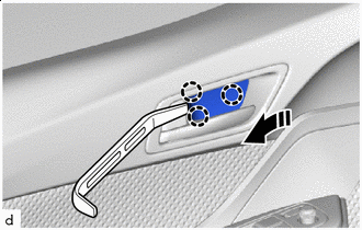

Remove in this Direction Using a moulding remover A, disengage the claws to remove the front door inside handle bezel plug as shown in the illustration.
-
-
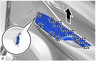
REMOVE MULTIPLEX NETWORK MASTER SWITCH ASSEMBLY WITH FRONT ARMREST BASE UPPER PANEL (for Driver Side)
-
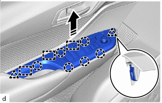
Remove in this Direction Disengage the claws, clips and guides as shown in the illustration.
-
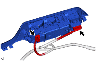
Disconnect the 2 connectors to remove the multiplex network master switch assembly with front armrest base upper panel.
-
-
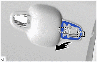
REMOVE POWER WINDOW REGULATOR SWITCH ASSEMBLY WITH FRONT ARMREST BASE UPPER PANEL (for Front Passenger Side)
-
Remove in this Direction Disengage the claws, clips and guides as shown in the illustration.
-
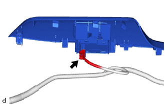
Disconnect the connector to remove the power window regulator switch assembly with front armrest base upper panel.
-
-
REMOVE FRONT DOOR TRIM BOARD SUB-ASSEMBLY
-
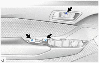
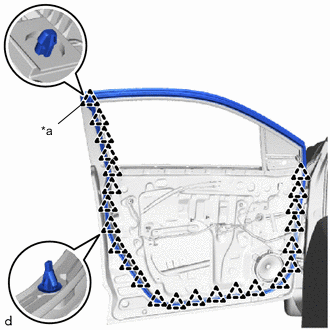
Remove the 3 screws.
-
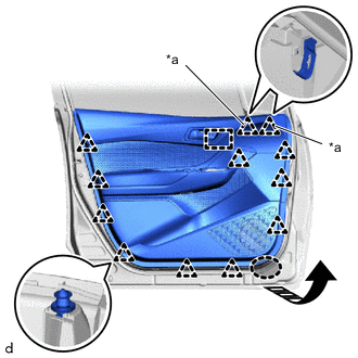
*a Clip (A) 
Place Hands Here Remove in this Direction Disengage the clips (A), other clips and guide as shown in the illustration.
-
Remove in this Direction Disengage the front door trim board sub-assembly with the front door glass inner weatherstrip and front door belt seal as shown in the illustration.
-
w/ Illumination:
-
Disconnect the connector.
-
-
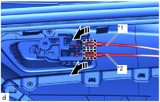
*1 Front Door Inside Locking Cable Assembly *2 Front Door Lock Remote Control Cable Assembly Remove in this Direction Disengage the guides to disconnect the front door inside locking cable assembly and front door lock remote control cable assembly to remove the front door trim board sub-assembly as shown in the illustration.
-
-
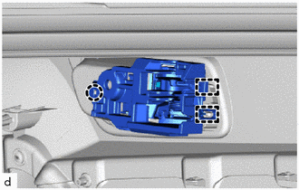
REMOVE FRONT DOOR INSIDE HANDLE SUB-ASSEMBLY
-
Disengage the claw and guides to remove the front door inside handle sub-assembly.
-
-
REMOVE NO. 1 INTERIOR ILLUMINATION LIGHT ASSEMBLY (w/ Illumination)
-
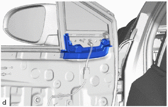
REMOVE FRONT DOOR LOWER FRAME BRACKET GARNISH
-
Disengage the clips to remove the front door lower frame bracket garnish.
-
-
REMOVE FRONT DOOR GLASS INNER WEATHERSTRIP
-
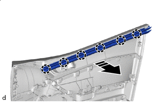
Remove in this Direction Disengage the claws remove the front door glass inner weatherstrip with the front door belt seal as shown in the illustration.
-
-
REMOVE FRONT DOOR BELT SEAL
-
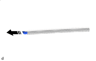
Remove in this Direction Remove the front door belt seal from the front door glass inner weatherstrip as shown in the illustration.
-
-
REMOVE FRONT DOOR VENT SEAL
-
Remove the front door vent seal.
-
-
REMOVE OUTER REAR VIEW MIRROR ASSEMBLY
-
REMOVE OUTER MIRROR PROTECTOR
-
Remove in this Direction Remove the 2 screws.
-
Disengage the claws to remove the outer mirror protector as shown in the illustration.
-
-
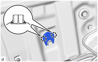
REMOVE FRONT DOOR SERVICE HOLE COVER
-
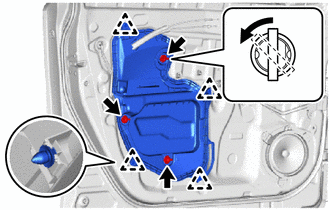
Turn the 3 door weatherstrip clips 45° and remove it clips as shown in the illustration.
-
Disengage the clips to remove the front door service hole cover.
-
-
REMOVE DOOR SIDE AIRBAG SENSOR
-
REMOVE FRONT DOOR GLASS SUB-ASSEMBLY
-
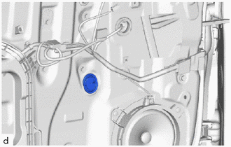
Remove the hole plug.
-
for Driver Side:
-
Connect the multiplex network master switch assembly.
-
Connect the cable to the negative (-) auxiliary battery terminal.
-
Move the front door glass sub-assembly so that the door glass bolts can be seen.
-
Disconnect the cable from the negative (-) auxiliary battery terminal.
-
Disconnect the multiplex network master switch assembly.
-
-
for Front Passenger Side:
-
Connect the power window regulator switch assembly.
-
Connect the cable to the negative (-) auxiliary battery terminal.
-
Move the front door glass sub-assembly so that the door glass bolts can be seen.
-
Disconnect the cable from the negative (-) auxiliary battery terminal.
-
Disconnect the power window regulator switch assembly.
-
-
Remove the 2 bolts.
Note
After the bolts are removed, do not allow the front door glass sub-assembly to fall.
-
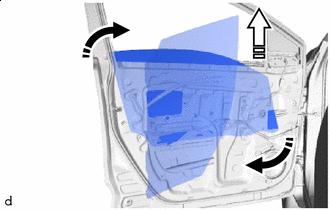
Remove in this Direction (1) 
Remove in this Direction (2) Remove the front door glass sub-assembly as shown in the illustration.
Note
Do not damage the front door glass sub-assembly.
-
-
REMOVE NO. 2 FRONT DOOR SERVICE HOLE COVER
-
Disengage the claws to remove the No. 2 front door service hole cover.
-
-
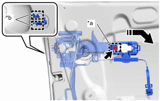
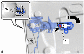
REMOVE FRONT DOOR WINDOW REGULATOR ASSEMBLY
-
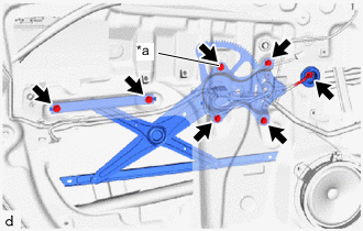
*a Temporary Bolt Disconnect the connector.
-
Loosen the temporary bolt.
Note
Do not remove the temporary bolt. If the temporary bolt is removed, the front door window regulator assembly may fall and cause damage.
-
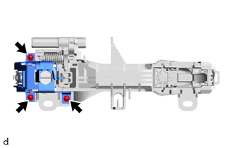
Remove the 5 bolts and front door window regulator sub-assembly.
-
Remove the temporary bolt from the front door window regulator assembly.
-
-
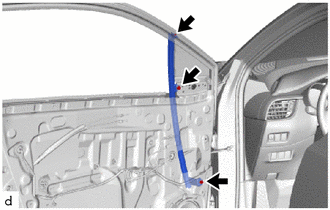
REMOVE DOOR FRAME UPPER GARNISH
-
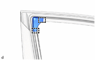
Disengage the guides to remove the door frame upper garnish.
-
-
REMOVE FRONT DOOR GLASS RUN
-
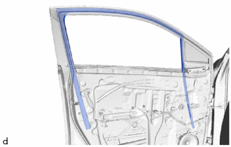
Remove the front door glass run.
-
-
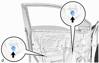
REMOVE FRONT DOOR FRONT LOWER FRAME SUB-ASSEMBLY
-
Raise up the front door weatherstrip.
-
Remove the screw.
-
Remove the 2 bolts and front door front lower frame sub-assembly.
-
Install the front door weatherstrip.
-
-
REMOVE FRONT DOOR REAR LOWER FRAME SUB-ASSEMBLY
-
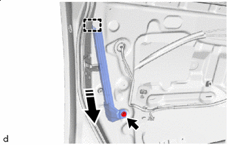
Remove in this Direction Remove the bolt.
-
Disengage the guide to remove the front door rear lower frame sub-assembly as shown in the illustration.
-
-
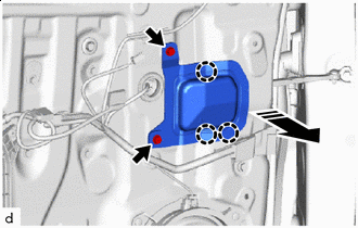
REMOVE FRONT DOOR OUTSIDE HANDLE COVER (for Driver Side)
-
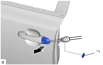
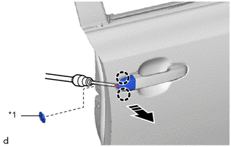
*1 Hole Plug Remove in this Direction Remove the hole plug.
-
Using a T30 "TORX" socket wrench, loosen the screw.
-
Remove the front door outside handle cover with front door lock cylinder assembly as shown in the illustration.
-
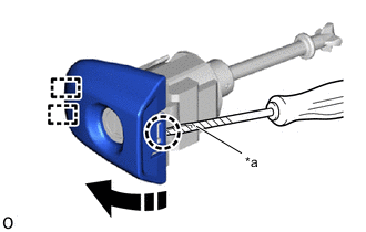
*a Protective Tape Remove in this Direction Using a screwdriver with its tip wrapped in protective tape, disengage the claw and guides to remove the front door outside handle cover as shown in the illustration.
-
-
REMOVE FRONT DOOR OUTSIDE HANDLE COVER (for Front Passenger Side)
-
*1 Hole Plug Remove in this Direction Remove the hole plug.
-
Using a T30 "TORX" socket wrench, loosen the screw.
-
Disengage the claws to remove the front door outside handle cover as shown in the illustration.
-
-
REMOVE FRONT DOOR OUTSIDE HANDLE ASSEMBLY
-
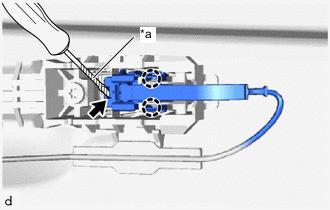
*a Protective Tape w/ Entry and Start System:
-
Disengage the claws.
-
Using a screwdriver with its tip wrapped in protective tape, disconnect the connector.
-
-
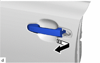
Remove in this Direction Remove the front door outside handle assembly as shown in the illustration.
-
-
REMOVE FRONT DOOR FRONT OUTSIDE HANDLE PAD
-
Remove in this Direction Disengage the claws and guide to remove the front door front outside handle pad as shown in the illustration.
-
-
REMOVE FRONT DOOR REAR OUTSIDE HANDLE PAD
-
Remove in this Direction Disengage the guides to remove the front door rear outside handle pad as shown in the illustration.
-
-
REMOVE FRONT DOOR LOCK WITH MOTOR ASSEMBLY
-
REMOVE FRONT DOOR OUTSIDE HANDLE FRAME SUB-ASSEMBLY
-
w/ Entry and Start System:
-
*a Grommet *b Guide Remove in this Direction Using a T30 "TORX" socket wrench, loosen the screw.
-
Disengage the grommet and guides to separate the front door outside handle frame sub-assembly as shown in the illustration.
-
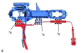
*a Guide *b Clamp Disengage the clamps and guide to remove the front door outside handle frame sub-assembly.
-
-
w/o Entry and Start System:
-
*a Grommet *b Guide Remove in this Direction Using a T30 "TORX" socket wrench, loosen the screw.
-
Disengage the grommet and guides to remove the front door outside handle frame sub-assembly as shown in the illustration.
-
-
w/ Protector:
-
Remove the 3 screws and door outside handle protector.
-
-
-
REMOVE FRONT DOOR LOCK OPEN ROD
-
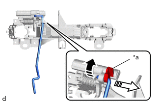
*a Snap Remove in this Direction (1) Remove in this Direction (2) Disengage the snap to remove the front door lock open rod from the front door outside frame sub-assembly as shown in the illustration.
-
-
REMOVE FRONT DOOR CHECK ASSEMBLY
-
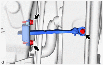
Remove the 3 bolts and front door check assembly.
-
-
REMOVE FRONT DOOR WEATHERSTRIP
-
*a Clip (A) Using a clip remover, disengage the clip (A) and other clips to remove the front door weatherstrip.
-
-
REMOVE FRONT DOOR DUST PROOF SEAL
-
Remove the 3 front door dust proof seals.
-
-
REMOVE FRONT NO. 1 SPEAKER ASSEMBLY (w/ Speaker)
-
REMOVE FRONT SPEAKER COVER (w/o Speaker)
-
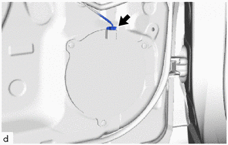
Disconnect the connector.
-
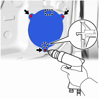
Using a drill bit with a diameter of less than 5 mm (0.197 in.), drill out the 3 rivet heads.
Note
-
Do not drill the rivet at an angle as this will cause damage to the drill and rivet installation hole. Line up the drill with the rivet, and carefully drill out the rivet head.
-
Be careful as the drilled rivet will be very hot.
-
-
Continue drilling and push out the remaining rivet fragments.
-
Using a vacuum cleaner, remove the rivet fragments and shavings from the inside of the door.
-
Disengage the claw and guide to remove the front speaker cover.
-
-
REMOVE FRONT DOOR FIX WINDOW GLASS
-
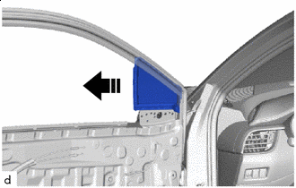
Remove in this Direction Remove the front door fix window glass with front door fix window weatherstrip as shown in the illustration.
-
-
REMOVE FRONT DOOR FIX WINDOW WEATHERSTRIP
-
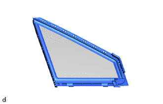
Remove the front door fix window weatherstrip from the front door fix window glass.
-
-
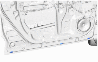
REMOVE FRONT DOOR PANEL CUSHION
-
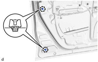
Using a clip remover, disengage the claws to remove the 2 front door panel cushions.
-
-
REMOVE FRONT DOOR OUTSIDE MOULDING
-
REMOVE FRONT DOOR OUTSIDE MOULDING SUB-ASSEMBLY
-
REMOVE HOLE CAP
-
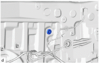
Remove the hole cap.
-
-
REMOVE FRONT DOOR BELT MOULDING ASSEMBLY
-
REMOVE FRONT DOOR SCUFF PLATE
-
REMOVE COWL SIDE TRIM BOARD
-
REMOVE FRONT DOOR FRONT WINDOW FRAME MOULDING
-
REMOVE FRONT DOOR UPPER WINDOW FRAME MOULDING
-
REMOVE NO. 4 FRONT DOOR STRIPE
-
REMOVE FRONT DOOR OUTSIDE STRIPE
-
REMOVE NO. 2 FRONT DOOR STRIPE