WINDSHIELD DEICER SYSTEM Windshield Deicer does not Operate
DESCRIPTION
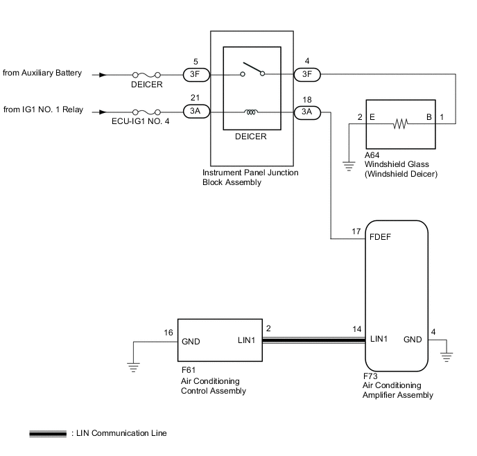
When the windshield deicer switch on the air conditioning control assembly is pressed, the operation signal is transmitted to the air conditioning amplifier assembly. via LIN communication. When the air conditioning amplifier assembly receives the signal, it turns on the DEICER relay to operate the windshield deicer system.
WIRING DIAGRAM
CAUTION / NOTICE / HINT
Note
-
Inspect the fuses for circuits related to this system before performing the following procedure.
-
If the auxiliary battery voltage becomes low, windshield deicer operation is canceled to prioritize supplying power to the power steering system.
PROCEDURE
-
CHECK AIR CONDITIONING SYSTEM
-
Check air conditioning system.
Tech Tips
Both the windshield deicer system operation signal and air conditioning system operation signal are transmitted to the air conditioning amplifier assembly via the same communication line.
OK The air conditioning system operates normally. Result Proceed to OK NG
NG 
GO TO AIR CONDITIONING SYSTEM Click here
OK 
-
-
PERFORM ACTIVE TEST USING GTS
-
Using the GTS, perform the Active Test.
Body Electrical > Air Conditioner > Active TestTester Display Measurement Item Control Range Diagnostic Note Deicer Relay (Front) Windshield glass (windshield deicer) OFF or ON -
Body Electrical > Air Conditioner > Active TestTester Display Deicer Relay (Front) OK The windshield deicer system operates normally. Result Proceed to OK NG
NG 
CHECK HARNESS AND CONNECTOR (INSTRUMENT PANEL JUNCTION BLOCK ASSEMBLY - AUXILIARY BATTERY) Click here
OK
-
-
REPLACE AIR CONDITIONING CONTROL ASSEMBLY
-
Replace sir conditioning control assembly with a new or known good one.
-
Check that the window defogger system operates normally.
Result Proceed to OK NG
OK
END (AIR CONDITIONING CONTROL ASSEMBLY WAS DEFECTIVE)
NG
REPLACE AIR CONDITIONING AMPLIFIER ASSEMBLY Click here
-
-
CHECK HARNESS AND CONNECTOR (INSTRUMENT PANEL JUNCTION BLOCK ASSEMBLY - AUXILIARY BATTERY)
-
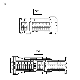
*a Front view of wire harness connector
(to Instrument Panel Junction Block Assembly)
Disconnect the 3F and 3A instrument panel junction block assembly connectors.
-
Measure the voltage according to the value(s) in the table below.
Standard Voltage Tester Connection Switch Condition Specified Condition 3F-5 - Body ground Power switch off 11 to 14 V 3A-21 - Body ground Power switch on (IG) 11 to 14 V Result Proceed to OK NG
NG
REPAIR OR REPLACE HARNESS OR CONNECTOR
OK
-
-
CHECK HARNESS AND CONNECTOR (INSTRUMENT PANEL JUNCTION BLOCK ASSEMBLY - AIR CONDITIONING AMPLIFIER)
-
Disconnect the 3A instrument panel junction block assembly connector.
-
Disconnect the F73 air conditioning amplifier assembly connector.
-
Measure the resistance according to the value(s) in the table below.
Standard Resistance Tester Connection Condition Specified Condition 3A-18 - F73-17 (FDEF) Always Below 1 Ω 3A-18 or F73-17 (FDEF) - Body ground Always 10 kΩ or higher Result Proceed to OK NG
NG
REPAIR OR REPLACE HARNESS OR CONNECTOR
OK
-
-
INSPECT INSTRUMENT PANEL JUNCTION BLOCK ASSEMBLY
-
Remove the instrument panel junction block assembly.
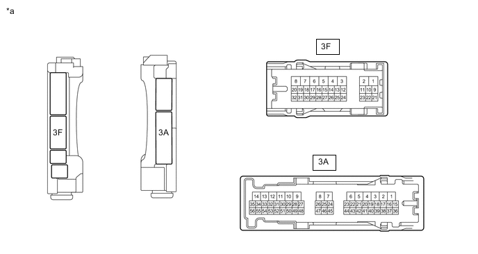
*a Component without harness connected (Instrument Panel Junction Block) - - -
Measure the resistance according to the value(s) in the table below.
Standard Resistance Tester Connection Condition Specified Condition 3F-5 - 3F-4 Auxiliary battery voltage applied between terminals 3A-21 and 3A-18 Below 1 Ω Auxiliary battery voltage not applied between terminals 3A-21 and 3A-18 10 kΩ or higher Result Proceed to OK NG
NG
REPLACE INSTRUMENT PANEL JUNCTION BLOCK ASSEMBLY Click here
OK
-
-
CHECK HARNESS AND CONNECTOR (INSTRUMENT PANEL JUNCTION BLOCK ASSEMBLY -WINDSHIELD GLASS (WINDSHIELD DEICER))
-
Disconnect the A64 windshield glass (windshield deicer) connector.
-
Disconnect the 3F instrument panel junction block.
-
Measure the voltage according to the value(s) in the table below.
Standard resistance Tester Connection Condition Specified Condition 3F-4 - A64-1(B) Always Below 1 Ω 3F-4 or A64-1(B) - Body ground Always 10 kΩ or higher Result Proceed to OK NG
NG
REPAIR OR REPLACE HARNESS OR CONNECTOR
OK
-
-
CHECK HARNESS AND CONNECTOR (WINDSHIELD GLASS [WINDSHIELD DEICER] - BODY GROUND)
-
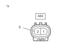
*a Front view of wire harness connector
(to Windshield Glass [Windshield Deicer])
Disconnect the windshield glass (windshield deicer) connector.
-
Measure the resistance according to the value(s) in the table below.
Standard Resistance Tester Connection Condition Specified Condition A64-2 (E) - Body ground Always Below 1 Ω Result Proceed to OK NG
OK
REPLACE WINDSHIELD GLASS (WINDSHIELD DEICER) Click here
NG
REPAIR OR REPLACE HARNESS OR CONNECTOR
-