CAN COMMUNICATION SYSTEM Check Bus 5 Lines for Short Circuit
DESCRIPTION
There may be a short circuit between the CAN main bus lines and/or CAN branch lines when the resistance between terminals 15 (CA5H) and 16 (CA5L) of the central gateway ECU (network gateway ECU) is below 54 Ω.
| Symptom | Trouble Area |
|---|---|
| Resistance between terminals 15 (CA5H) and 16 (CA5L) of the central gateway ECU (network gateway ECU) is below 54 Ω. |
|
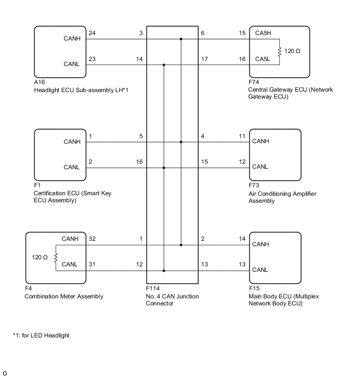
WIRING DIAGRAM
CAUTION / NOTICE / HINT
Note
-
Because the order of diagnosis is important to allow correct diagnosis, make sure to begin troubleshooting using How to Proceed with Troubleshooting when CAN communication system related DTCs are output.
-
Before measuring the resistance of the CAN bus, turn the power switch off and leave the vehicle for 1 minute or more without operating the key or any switches, or opening or closing the doors. After that, disconnect the cable from the negative (-) auxiliary battery terminal and leave the vehicle for 1 minute or more before measuring the resistance.
-
After turning the power switch off, waiting time may be required before disconnecting the cable from the negative (-) auxiliary battery terminal. Therefore, make sure to read the disconnecting the cable from the negative (-) auxiliary battery terminal notices before proceeding with work.
-
After performing repairs, perform the DTC check procedure and confirm that the DTCs are not output again.
DTC check procedure: Turn the power switch on (IG), turn the blind spot monitor system on using the blind spot monitor main switch (ON/OFF switch), turn the LDA main switch on and wait for approximately 20 seconds or more.
-
After the repair, perform the CAN bus check and check that all the ECUs and sensors connected to the CAN communication system are displayed as normal.
-
Before replacing the main body ECU (multiplex network body ECU) or certification ECU (smart key ECU assembly), refer to Service Bulletin.
-
When replacing the combination meter assembly, always replace it with a new one. If a combination meter assembly which was installed to another vehicle is used, the information stored in it will not match the information from the vehicle and a DTC may be stored.
Tech Tips
-
Before disconnecting related connectors for inspection, push in on each connector body to check that the connector is not loose or disconnected.
-
When a connector is disconnected, check that the terminals and connector body are not cracked, deformed or corroded.
PROCEDURE
-
CHECK FOR SHORT IN CAN BUS LINES (NO. 4 CAN JUNCTION CONNECTOR)
-
Disconnect the cable from the negative (-) auxiliary battery terminal.
-
Disconnect the No. 4 CAN junction connector.
-
Measure the resistance according to the value(s) in the table below.
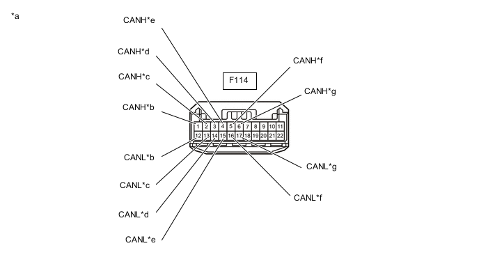
*a Front view of wire harness connector
(to No. 4 CAN Junction Connector)
*b to Combination Meter Assembly *c to Main Body ECU (Multiplex Network Body ECU) *d to Headlight ECU Sub-assembly LH
(for LED Headlight)
*e to Air Conditioning Amplifier Assembly *f to Certification ECU (Smart Key ECU Assembly) *g to Central Gateway ECU (Network Gateway ECU) - - Standard Resistance Tester Connection Condition Specified Condition Connected to F114-1 (CANH) - F114-12 (CANL) Cable disconnected from negative (-) auxiliary battery terminal 108 to 132 Ω Combination meter assembly F114-2 (CANH) - F114-13 (CANL) Cable disconnected from negative (-) auxiliary battery terminal 200 Ω or higher Main body ECU (multiplex network body ECU) F114-3 (CANH) - F114-14 (CANL) Cable disconnected from negative (-) auxiliary battery terminal 200 Ω or higher Headlight ECU sub-assembly LH*1 F114-4 (CANH) - F114-15 (CANL) Cable disconnected from negative (-) auxiliary battery terminal 200 Ω or higher Air conditioning amplifier assembly F114-5 (CANH) - F114-16 (CANL) Cable disconnected from negative (-) auxiliary battery terminal 200 Ω or higher Certification ECU (smart key ECU assembly) F114-6 (CANH) - F114-17 (CANL) Cable disconnected from negative (-) auxiliary battery terminal 108 to 132 Ω Central gateway ECU (network gateway ECU)
-
*1: for LED Headlight
Result Result Proceed to OK A NG (Line to central gateway ECU (network gateway ECU)) B NG (Line to combination meter assembly) C NG (Line to ECU or sensor) D -
A 
REPLACE NO. 4 CAN JUNCTION CONNECTOR
C 
CHECK FOR SHORT IN CAN BUS LINES (NO. 4 CAN JUNCTION CONNECTOR - COMBINATION METER ASSEMBLY) Click here
D
CHECK FOR SHORT IN CAN BUS LINES (ECU OR SENSOR) Click here
B 
-
-
CHECK FOR SHORT IN CAN BUS LINES (NO. 4 CAN JUNCTION CONNECTOR - CENTRAL GATEWAY ECU (NETWORK GATEWAY ECU))
-
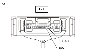
Disconnect the F74 central gateway ECU (network gateway ECU) connector.
-
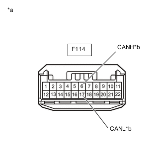
*a Front view of wire harness connector
(to No. 4 CAN Junction Connector)
*b to Central Gateway ECU (Network Gateway ECU) Measure the resistance according to the value(s) in the table below.
Standard Resistance Tester Connection Condition Specified Condition F114-6 (CANH) - F114-17 (CANL) Cable disconnected from negative (-) auxiliary battery terminal 1 MΩ or higher Result Result Proceed to OK (for LHD) A OK (for RHD) B NG C
A
REPLACE CENTRAL GATEWAY ECU (NETWORK GATEWAY ECU) Click here
B
REPLACE CENTRAL GATEWAY ECU (NETWORK GATEWAY ECU) Click here
C
REPAIR OR REPLACE CAN MAIN BUS LINES OR CONNECTOR (NO. 4 CAN JUNCTION CONNECTOR - CENTRAL GATEWAY ECU (NETWORK GATEWAY ECU))
-
-
CHECK FOR SHORT IN CAN BUS LINES (NO. 4 CAN JUNCTION CONNECTOR - COMBINATION METER ASSEMBLY)
-
Disconnect the F4 combination meter assembly connector.
-
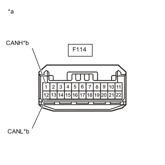
*a Front view of wire harness connector
(to No. 4 CAN Junction Connector)
*b to Combination Meter Assembly Measure the resistance according to the value(s) in the table below.
Standard Resistance Tester Connection Condition Specified Condition F114-1 (CANH) - F114-12 (CANL) Cable disconnected from negative (-) auxiliary battery terminal 1 MΩ or higher Result Result OK NG
OK
REPLACE COMBINATION METER ASSEMBLY Click here
NG
REPAIR OR REPLACE CAN MAIN BUS LINES OR CONNECTOR (NO. 4 CAN JUNCTION CONNECTOR - COMBINATION METER ASSEMBLY)
-
-
CHECK FOR SHORT IN CAN BUS LINES (ECU OR SENSOR)
-
Reconnect all wire harness connectors.
-
Disconnect the connector that includes terminals CANH and CANL from the ECU or sensor to which the short circuited branch line is connected.
-
*a Component with harness connected
(Central Gateway ECU (Network Gateway ECU))
Measure the resistance according to the value(s) in the table below.
Standard Resistance Tester Connection Condition Specified Condition F74-15 (CA5H) - F74-16 (CA5L) Cable disconnected from negative (-) auxiliary battery terminal 54 to 69 Ω Tech Tips
-
If the resistance becomes normal (between 54 and 69 Ω) when the connector is disconnected from the ECU or sensor, there may be a short in the ECU or sensor.
-
If the resistance does not become normal when the connector is disconnected from the ECU or sensor, check for a short in the wire harness and repair or replace the wire harness or connector if necessary.
Result Result OK NG -
OK
REPLACE ECU OR SENSOR
NG
REPAIR OR REPLACE HARNESS OR CONNECTOR
-