CAN COMMUNICATION SYSTEM Motor Generator Control ECU Communication Stop Mode
Info Added 2017-10-06 ![]()
DESCRIPTION
| Detection Item | Symptom | Trouble Area |
|---|---|---|
| Motor Generator Control ECU Communication Stop Mode | Any of the following conditions are met:
|
|
WIRING DIAGRAM
-
for LHD
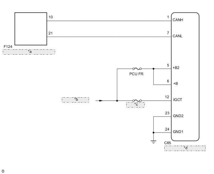
*a No. 10 CAN Junction Connector *b from IGCT Relay *c IGCT NO. 2 *d Inverter with Converter Assembly -
for RHD
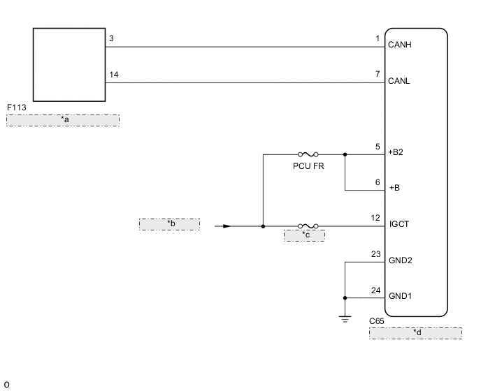
*a No. 3 CAN Junction Connector *b from IGCT Relay *c IGCT NO. 2 *d Inverter with Converter Assembly
CAUTION / NOTICE / HINT
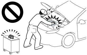
CAUTION:
-
Before the following operations are conducted, take precautions to prevent electric shock by turning the power switch off, wearing insulated gloves, and removing the service plug grip from HV battery.
-
Inspecting the high-voltage system
-
Disconnecting the low voltage connector of the inverter with converter assembly
-
Disconnecting the low voltage connector of the HV battery
-
To prevent electric shock, make sure to remove the service plug grip to cut off the high voltage circuit before servicing the vehicle.
-
After removing the service plug grip from the HV battery, put it in your pocket to prevent other technicians from accidentally reconnecting it while you are working on the high-voltage system.
-
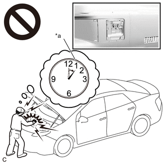
*a Without waiting for 10 minutes After removing the service plug grip, wait for at least 10 minutes before touching any of the high-voltage connectors or terminals. After waiting for 10 minutes, check the voltage at the terminals in the inspection point in the inverter with converter assembly. The voltage should be 0 V before beginning work.
Tech Tips
Waiting for at least 10 minutes is required to discharge the high-voltage capacitor inside the inverter with converter assembly.
Note
After turning the power switch off, waiting time may be required before disconnecting the cable from the negative (-) auxiliary battery terminal. Therefore, make sure to read the disconnecting the cable from the negative (-) auxiliary battery terminal notices before proceeding with work.
Note
-
Because the order of diagnosis is important to allow correct diagnosis, make sure to begin troubleshooting using How to Proceed with Troubleshooting when CAN communication system related DTCs are output.
-
Before measuring the resistance of the CAN bus, turn the power switch off and leave the vehicle for 1 minute or more without operating the key or any switches, or opening or closing the doors. After that, disconnect the cable from the negative (-) auxiliary battery terminal and leave the vehicle for 1 minute or more before measuring the resistance.
-
After turning the power switch off, waiting time may be required before disconnecting the cable from the negative (-) auxiliary battery terminal. Therefore, make sure to read the disconnecting the cable from the negative (-) auxiliary battery terminal notices before proceeding with work.
-
After performing repairs, perform the DTC check procedure and confirm that the DTCs are not output again.
DTC check procedure: Turn the power switch on (IG) and wait at least approximately 8 seconds.
-
After the repair, perform the CAN bus check and check that all the ECUs and sensors connected to the CAN communication system are displayed as normal.
-
Inspect the fuses for circuits related to this system before performing the following procedure.
Tech Tips
-
Before disconnecting related connectors for inspection, push in on each connector body to check that the connector is not loose or disconnected.
-
When a connector is disconnected, check that the terminals and connector body are not cracked, deformed or corroded.
PROCEDURE
-
CHECK FOR OPEN IN CAN BUS LINES (INVERTER WITH CONVERTER ASSEMBLY BRANCH LINE)
CAUTION:
Be sure to wear insulated gloves.
-
Check that the service plug grip is not installed.
Note
After removing the service plug grip, do not turn the power switch on (READY), unless instructed by the repair manual because this may cause a malfunction.
-
Disconnect the cable from the negative (-) auxiliary battery terminal.
-
Disconnect the inverter with converter assembly connector.
-
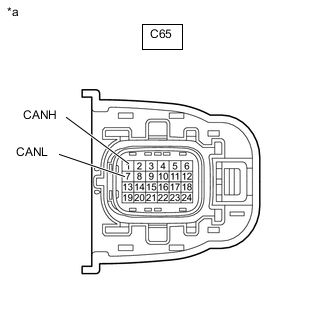
*a Front view of wire harness connector
(to Inverter with Converter Assembly)
Measure the resistance according to the value(s) in the table below.
Standard Resistance Tester Connection Condition Specified Condition C65-1 (CANH) - C65-7 (CANL) Cable disconnected from negative (-) auxiliary battery terminal 54 to 69 Ω Result Result OK NG
NG 
REPAIR OR REPLACE CAN BRANCH LINES OR CONNECTOR (INVERTER WITH CONVERTER ASSEMBLY)
OK 
-
-
CHECK HARNESS AND CONNECTOR (POWER SOURCE CIRCUIT)
-
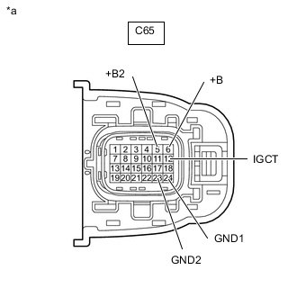
*a Front view of wire harness connector
(to Inverter with Converter Assembly)
Measure the resistance according to the value(s) in the table below.
Standard Resistance Tester Connection Condition Specified Condition C65-23 (GND2) - Body ground Cable disconnected from negative (-) auxiliary battery terminal Below 1 Ω C65-24 (GND1) - Body ground Cable disconnected from negative (-) auxiliary battery terminal Below 1 Ω -
Reconnect the cable to the negative (-) auxiliary battery terminal.
-
Measure the voltage according to the value(s) in the table below.
Standard Voltage Tester Connection Switch Condition Specified Condition C65-5 (+B2) - Body ground Power switch on (IG) 11 to 14 V C65-6 (+B) - Body ground Power switch on (IG) 11 to 14 V C65-12 (IGCT) - Body ground Power switch on (IG) 11 to 14 V Result Result OK NG
OK
REPLACE INVERTER WITH CONVERTER ASSEMBLY Click here
NG
REPAIR OR REPLACE HARNESS OR CONNECTOR (POWER SOURCE CIRCUIT)
-