CAN COMMUNICATION SYSTEM Skid Control ECU Communication Stop Mode
DESCRIPTION
| Detection Item | Symptom | Trouble Area |
|---|---|---|
| Skid Control ECU Communication Stop Mode | Any of the following conditions are met:
|
|
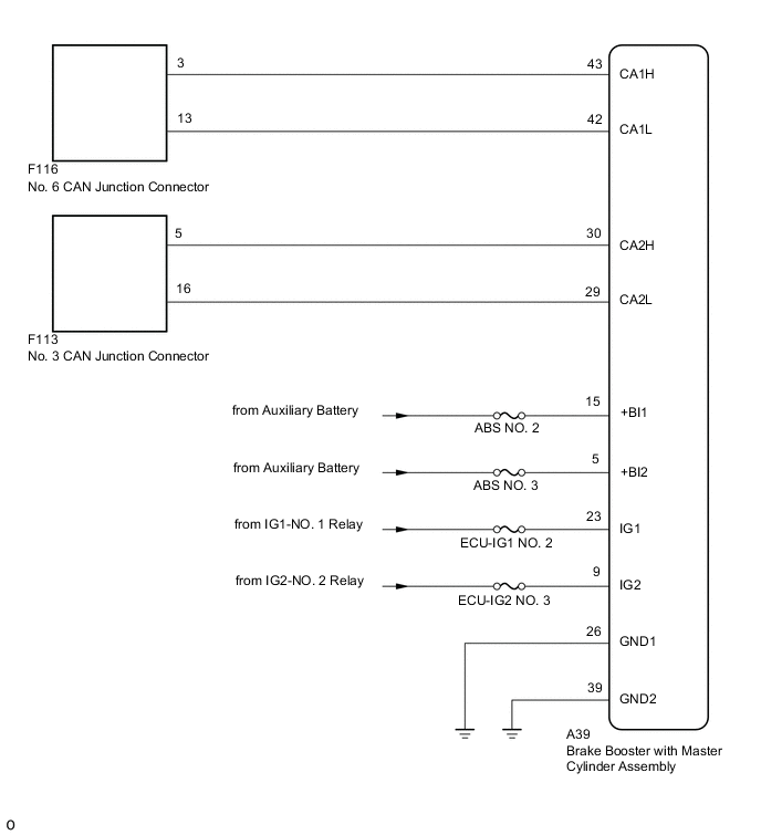
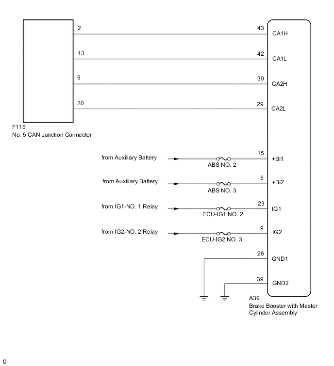
WIRING DIAGRAM
-
for LHD
-
for RHD
CAUTION / NOTICE / HINT
Note
-
Because the order of diagnosis is important to allow correct diagnosis, make sure to begin troubleshooting using How to Proceed with Troubleshooting when CAN communication system related DTCs are output.
-
Before measuring the resistance of the CAN bus, turn the power switch off and leave the vehicle for 1 minute or more without operating the key or any switches, or opening or closing the doors. After that, disconnect the cable from the negative (-) auxiliary battery terminal and leave the vehicle for 1 minute or more before measuring the resistance.
-
After turning the power switch off, waiting time may be required before disconnecting the cable from the negative (-) auxiliary battery terminal. Therefore, make sure to read the disconnecting the cable from the negative (-) auxiliary battery terminal notices before proceeding with work.
-
After performing repairs, perform the DTC check procedure and confirm that the DTCs are not output again.
DTC check procedure: Turn the power switch on (IG), blind spot monitor system on using the blind spot monitor main switch (ON/OFF switch), turn the cruise control main switch on, turn the LDA main switch on and wait for approximately 61 seconds or more.
-
After the repair, perform the CAN bus check and check that all the ECUs and sensors connected to the CAN communication system are displayed as normal.
-
Inspect the fuses for circuits related to this system before performing the following procedure.
Tech Tips
-
Before disconnecting related connectors for inspection, push in on each connector body to check that the connector is not loose or disconnected.
-
When a connector is disconnected, check that the terminals and connector body are not cracked, deformed or corroded.
PROCEDURE
-
CHECK DTC (ELECTRONICALLY CONTROLLED BRAKE SYSTEM)
-
Connect the GTS to the DLC3.
-
Turn the power switch on (IG).
-
Turn the GTS on.
-
Enter the following menus: Chassis / ABS/VSC/TRC / Trouble Codes.
Chassis > ABS/VSC/TRC > Trouble Codes -
Check that DTC C1241 which indicates a malfunction in the power source circuit of the electronically controlled brake system is not stored by the electronically controlled brake system.
Result Result Proceed to DTC C1241 is not output A DTC C1241 is output B
B 
GO TO DIAGNOSTIC PROCEDURE INDICATED BY OUTPUT DTC Click here
A 
-
-
CHECK FOR OPEN IN CAN BUS LINES (BRAKE BOOSTER WITH MASTER CYLINDER ASSEMBLY BRANCH LINE)
-
Disconnect the cable from the negative (-) auxiliary battery terminal.
-
Disconnect the brake booster with master cylinder assembly connector.
-
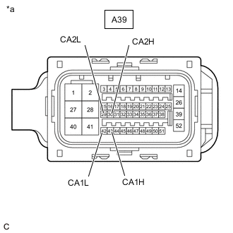
*a Front view of wire harness connector
(to Brake Booster with Master Cylinder Assembly)
Measure the resistance according to the value(s) in the table below.
Standard Resistance Tester Connection Condition Specified Condition A39-43 (CA1H) - A39-42 (CA1L) Cable disconnected from negative (-) auxiliary battery terminal 54 to 69 Ω A39-30 (CA2H) - A39-29 (CA2L) Cable disconnected from negative (-) auxiliary battery terminal 54 to 69 Ω Result Result OK NG
NG
REPAIR OR REPLACE CAN BRANCH LINES OR CONNECTOR (BRAKE BOOSTER WITH MASTER CYLINDER ASSEMBLY)
OK
-
-
CHECK HARNESS AND CONNECTOR (POWER SOURCE CIRCUIT)
-
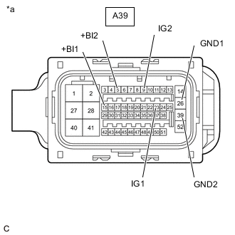
*a Front view of wire harness connector
(to Brake Booster with Master Cylinder Assembly)
Measure the resistance according to the value(s) in the table below.
Standard Resistance Tester Connection Condition Specified Condition A39-26 (GND1) - Body ground Cable disconnected from negative (-) auxiliary battery terminal Below 1 Ω A39-39 (GND2) - Body ground Cable disconnected from negative (-) auxiliary battery terminal Below 1 Ω -
Reconnect the cable to the negative (-) auxiliary battery terminal.
-
Measure the voltage according to the value(s) in the table below.
Standard Voltage Tester Connection Switch Condition Specified Condition A39-5 (+BI2) - Body ground Power switch off 11 to 14 V A39-15 (+BI1) - Body ground Power switch off 11 to 14 V A39-9 (IG2) - Body ground Power switch on (IG) 11 to 14 V A39-23 (IG1) - Body ground Power switch on (IG) 11 to 14 V Result Result Proceed to OK (for LHD) A OK (for RHD) B NG C
A
REPLACE BRAKE BOOSTER WITH MASTER CYLINDER ASSEMBLY Click here
B
REPLACE BRAKE BOOSTER WITH MASTER CYLINDER ASSEMBLY Click here
C
REPAIR OR REPLACE HARNESS OR CONNECTOR (POWER SOURCE CIRCUIT)
-