SIMPLE INTELLIGENT PARKING ASSIST SYSTEM, Diagnostic DTC:C1AF2
| DTC Code | DTC Name |
|---|---|
| C1AF2 | Rear Right Side Sensor |
DESCRIPTION
The rear side ultrasonic sensor (RH) is installed to the rear bumper. The clearance warning ECU assembly detects obstacles based on signals received from the rear side ultrasonic sensor (RH). If the rear side ultrasonic sensor (RH) has an open circuit or other malfunction, it will not function normally.
| DTC No. | Detection Item | DTC Detection Condition | Trouble Area |
|---|---|---|---|
| C1AF2 | Rear Right Side Sensor | Either condition is met (1 trip detection logic*):
|
|
-
*: Only output while a malfunction is present.
| Vehicle Condition | ||||
|---|---|---|---|---|
| Pattern 1 | Pattern 2 | Pattern 3 | ||
| Diagnosis Condition | Power switch on (IG) | ○ | ○ | ○ |
| Malfunction Status | A malfunction of the rear side ultrasonic sensor (RH) | ○ | - | - |
| A short in the harness or connector | - | ○ | - | |
| An open in the harness or connector | - | - | ○ | |
| Detection Time | - | - | - | |
| Number of Trips | 1 trip | 1 trip | 1 trip | |
Tech Tips
DTC will be output when conditions for either of the patterns in the table above are met.
WIRING DIAGRAM
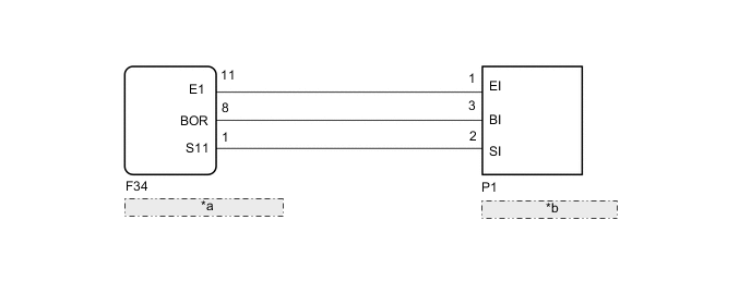
| *a | Clearance Warning ECU Assembly |
| *b | Rear Side Ultrasonic Sensor (RH) |
CAUTION / NOTICE / HINT
Note
-
If DTCs are output after repairs, turn the power switch on (IG) and the simple intelligent parking assist system on. Then clear the DTCs.
-
Depending on the parts that are replaced during vehicle inspection or maintenance, performing initialization may be needed. Refer to Calibration.
PROCEDURE
-
CHECK HARNESS AND CONNECTOR (CLEARANCE WARNING ECU ASSEMBLY - REAR SIDE ULTRASONIC SENSOR (RH))
-
Disconnect the F34 clearance warning ECU assembly connector.
-
Disconnect the P1 rear side ultrasonic sensor (RH) connector.
-
Measure the resistance according to the value(s) in the table below.
Standard Resistance Tester Connection Condition Specified Condition F34-11 (E1) - P1-1 (EI) Always Below 1 Ω F34-8 (BOR) - P1-3 (BI) Always Below 1 Ω F34-1 (S11) - P1-2 (SI) Always Below 1 Ω F34-11 (E1) - F34-1 (S11) Always 10 kΩ or higher F34-8 (BOR) - F34-1 (S11) Always 10 kΩ or higher F34-11 (E1) - F34-8 (BOR) Always 10 kΩ or higher Result Proceed to OK NG
NG 
REPAIR OR REPLACE HARNESS OR CONNECTOR
OK 
-
-
REPLACE REAR SIDE ULTRASONIC SENSOR (RH)
-
Replace the rear side ultrasonic sensor (RH) with a known good one.
Tech Tips
All of the sensors are interchangeable. To confirm whether a sensor is functioning normally, switch it with a known good sensor from the other end of the vehicle.
Result Proceed to NEXT
NEXT
-
-
CHECK DTC OUTPUT
-
Clear the DTCs.
Body Electrical > IPA/ICS/Clearance Sonar > Clear DTCs -
Check for DTCs.
Body Electrical > IPA/ICS/Clearance Sonar > Trouble CodesOK No DTCs are output. Result Proceed to OK NG
OK
END (REAR SIDE ULTRASONIC SENSOR (RH) WAS DEFECTIVE)
NG
REPLACE CLEARANCE WARNING ECU ASSEMBLY Click here
-