NAVIGATION SYSTEM Speaker Circuit
DESCRIPTION
-
If there is a short in a speaker circuit, the radio and display receiver assembly detects it and stops output to the speakers.
Thus sound cannot be heard from the speakers even if there is no malfunction in the radio and display receiver assembly, or speakers.
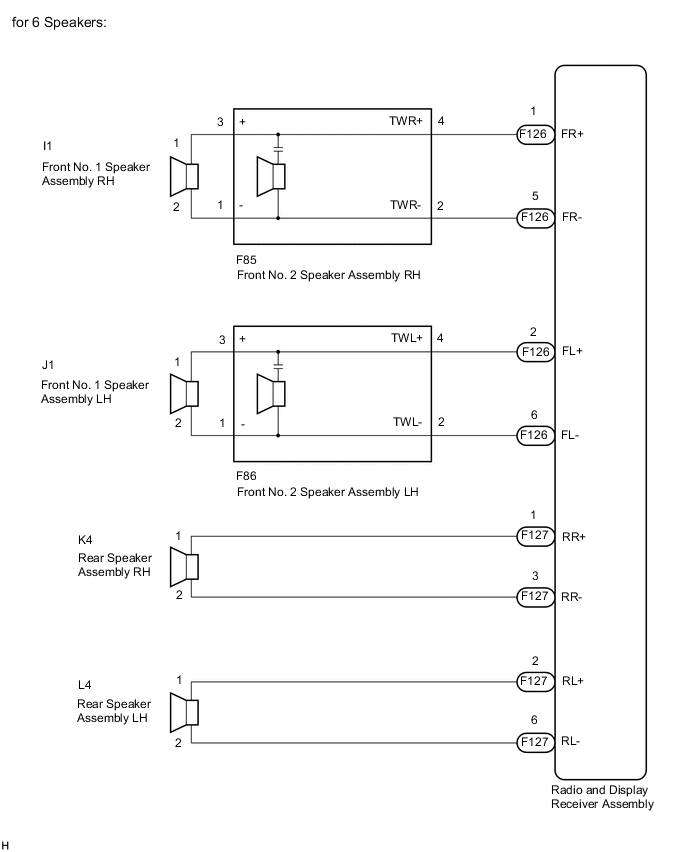
for 6 Speakers:
-
If there is a short in a speaker circuit, the stereo component amplifier assembly detects it and stops output to the speakers.
Thus sound cannot be heard from the speakers even if there is no malfunction in the stereo component amplifier assembly, or speakers.
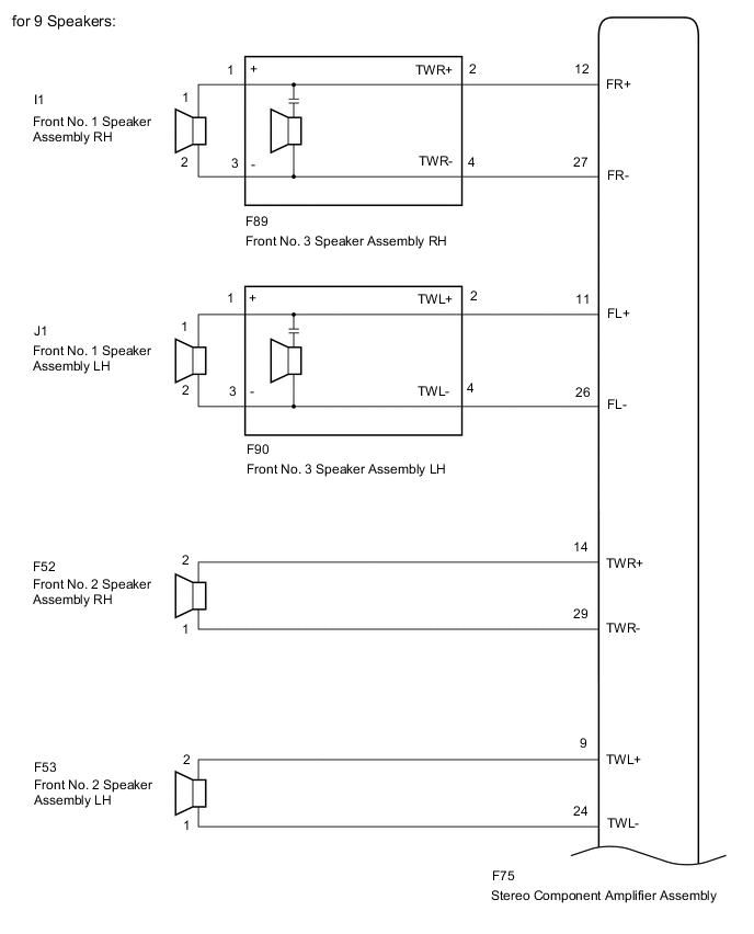
for 9 Speakers:
WIRING DIAGRAM
-
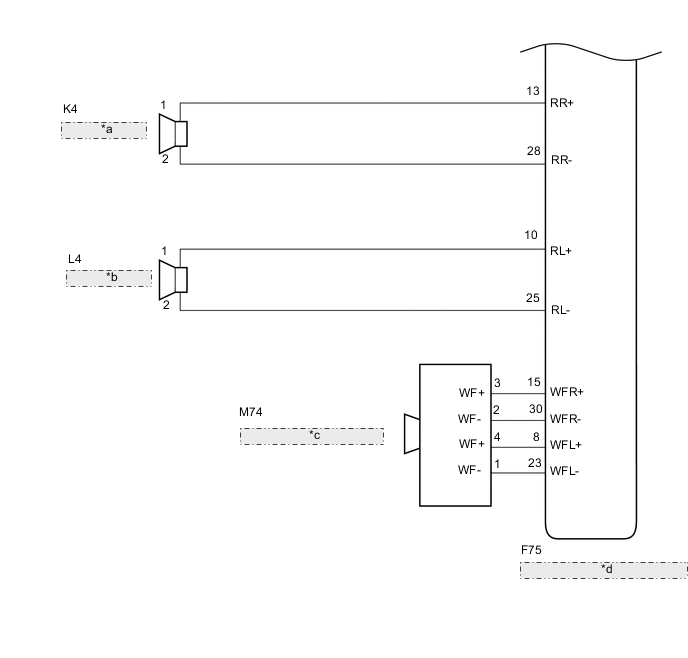
for 9 Speakers *a Rear Speaker Assembly RH *b Rear Speaker Assembly LH *c No. 1 Speaker with Box Assembly *d Stereo Component Amplifier Assembly
PROCEDURE
-
CONFIRM MODEL
-
Choose the model to be inspected.
Result Result Proceed to for 6 Speakers A for 9 Speakers B
B 
CHECK SPEAKER (OPERATION CHECK) Click here
A 
-
-
CHECK SPEAKER (OPERATION CHECK)
-
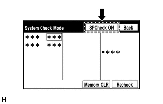
Enter the "System Check Mode" screen. Refer to Check Speaker in Operation Check.
-
Perform the operation check above and determine the speaker that is not operating.
Result Not Operating Speaker Proceed to Front No. 1 speaker assembly or front No. 2 speaker assembly A Rear speaker assembly B Tech Tips
If sound cannot be heard from any speaker, inspect all of them.
B
CHECK HARNESS AND CONNECTOR (RADIO AND DISPLAY RECEIVER ASSEMBLY - REAR SPEAKER ASSEMBLY) Click here
A
-
-
CHECK HARNESS AND CONNECTOR (RADIO AND DISPLAY RECEIVER ASSEMBLY - FRONT NO. 1 SPEAKER ASSEMBLY - FRONT NO. 2 SPEAKER ASSEMBLY)
-
Disconnect the F126 radio and display receiver assembly connector.
-
Disconnect the I1 and J1 front No. 1 speaker assembly connectors.
-
Disconnect the F85 and F86 front No. 2 speaker assembly connectors.
-
Measure the resistance according to the value(s) in the table below.
Standard Resistance Tester Connection Condition Specified Condition F126-1 (FR+) - F85-4 (TWR+) Always Below 1 Ω F126-5 (FR-) - F85-2 (TWR-) Always Below 1 Ω F126-2 (FL+) - F86-4 (TWL+) Always Below 1 Ω F126-6 (FL-) - F86-2 (TWL-) Always Below 1 Ω I1-1 - F85-3 (+) Always Below 1 Ω I1-2 - F85-1 (-) Always Below 1 Ω J1-1 - F86-3 (+) Always Below 1 Ω J1-2 - F86-1 (-) Always Below 1 Ω F126-1 (FR+) or F85-4 (TWR+) - Body ground Always 10 kΩ or higher F126-5 (FR-) or F85-2 (TWR-) - Body ground Always 10 kΩ or higher F126-2 (FL+) or F86-4 (TWL+) - Body ground Always 10 kΩ or higher F126-6 (FL-) or F86-2 (TWL-) - Body ground Always 10 kΩ or higher I1-1 or F85-3 (+) - Body ground Always 10 kΩ or higher I1-2 or F85-1 (-) - Body ground Always 10 kΩ or higher J1-1 or F86-3 (+) - Body ground Always 10 kΩ or higher J1-2 or F86-1 (-) - Body ground Always 10 kΩ or higher Result Proceed to OK NG
NG 
REPAIR OR REPLACE HARNESS OR CONNECTOR
OK
-
-
INSPECT FRONT NO. 2 SPEAKER ASSEMBLY
-
Remove the front No. 2 speaker assembly.
-
Inspect the front No. 2 speaker assembly.
-
Check that the malfunction disappears when a new or known good front No. 2 speaker assembly is installed.
OK Malfunction disappears. Result Proceed to OK NG
OK
END
NG
-
-
INSPECT FRONT NO. 1 SPEAKER ASSEMBLY
-
Remove the front No. 1 speaker assembly.
-
Inspect the front No. 1 speaker assembly.
Result Proceed to OK NG
OK
PROCEED TO NEXT SUSPECTED AREA SHOWN IN PROBLEM SYMPTOMS TABLE Click here
NG
REPLACE FRONT NO. 1 SPEAKER ASSEMBLY Click here
-
-
CHECK HARNESS AND CONNECTOR (RADIO AND DISPLAY RECEIVER ASSEMBLY - REAR SPEAKER ASSEMBLY)
-
Disconnect the F127 radio and display receiver assembly connector.
-
Disconnect the L4 and K4 rear speaker assembly connectors.
-
Measure the resistance according to the value(s) in the table below.
Standard Resistance Tester Connection Condition Specified Condition F127-1 (RR+) - K4-1 Always Below 1 Ω F127-3 (RR-) - K4-2 Always Below 1 Ω F127-2 (RL+) - L4-1 Always Below 1 Ω F127-6 (RL-) - L4-2 Always Below 1 Ω F127-1 (RR+) or K4-1 - Body ground Always 10 kΩ or higher F127-3 (RR-) or K4-2 - Body ground Always 10 kΩ or higher F127-2 (RL+) or L4-1 - Body ground Always 10 kΩ or higher F127-6 (RL-) or L4-2 - Body ground Always 10 kΩ or higher Result Proceed to OK NG
NG
REPAIR OR REPLACE HARNESS OR CONNECTOR
OK
-
-
INSPECT REAR SPEAKER ASSEMBLY
-
Remove the rear speaker assembly.
-
Inspect the rear speaker assembly.
Result Proceed to OK NG
OK
PROCEED TO NEXT SUSPECTED AREA SHOWN IN PROBLEM SYMPTOMS TABLE Click here
NG
REPLACE REAR SPEAKER ASSEMBLY Click here
-
-
CHECK SPEAKER (OPERATION CHECK)
-
Enter the "System Check Mode" screen. Refer to Check Speaker in Operation Check.
-
Perform the operation check above and determine the speaker that is not operating.
Result Not Operating Speaker Proceed to Front No. 1 speaker assembly or front No. 3 speaker assembly A Front No. 2 speaker assembly B Rear speaker assembly C No. 1 speaker with box assembly D Tech Tips
If sound cannot be heard from any speaker, inspect all of them.
B
CHECK HARNESS AND CONNECTOR (STEREO COMPONENT AMPLIFIER ASSEMBLY - FRONT NO. 2 SPEAKER ASSEMBLY) Click here
C
CHECK HARNESS AND CONNECTOR (STEREO COMPONENT AMPLIFIER ASSEMBLY - REAR SPEAKER ASSEMBLY) Click here
D
CHECK HARNESS AND CONNECTOR (STEREO COMPONENT AMPLIFIER ASSEMBLY - NO. 1 SPEAKER WITH BOX ASSEMBLY) Click here
A
-
-
CHECK HARNESS AND CONNECTOR (STEREO COMPONENT AMPLIFIER ASSEMBLY - FRONT NO. 1 SPEAKER ASSEMBLY - FRONT NO. 3 SPEAKER ASSEMBLY)
-
Disconnect the F75 stereo component amplifier assembly connector.
-
Disconnect the I1 and J1 front No. 1 speaker assembly connectors.
-
Disconnect the F89 and F90 front No. 3 speaker assembly connectors.
-
Measure the resistance according to the value(s) in the table below.
Standard Resistance Tester Connection Condition Specified Condition F75-12 (FR+) - F89-2 (TWR+) Always Below 1 Ω F75-27 (FR-) - F89-4 (TWR-) Always Below 1 Ω F75-11 (FL+) - F90-2 (TWL+) Always Below 1 Ω F75-26 (FL-) - F90-4 (TWL-) Always Below 1 Ω I1-1 - F89-1 (+) Always Below 1 Ω I1-2 - F89-3 (-) Always Below 1 Ω J1-1 - F90-1 (+) Always Below 1 Ω J1-2 - F90-3 (-) Always Below 1 Ω F75-12 (FR+) or F89-2 (TWR+) - Body ground Always 10 kΩ or higher F75-27 (FR-) or F89-4 (TWR-) - Body ground Always 10 kΩ or higher F75-11 (FL+) or F90-2 (TWL+) - Body ground Always 10 kΩ or higher F75-26 (FL-) or F90-4 (TWL-) - Body ground Always 10 kΩ or higher I1-1 or F89-1 (+) - Body ground Always 10 kΩ or higher I1-2 or F89-3 (-) - Body ground Always 10 kΩ or higher J1-1 or F90-1 (+) - Body ground Always 10 kΩ or higher J1-2 or F90-3 (-) - Body ground Always 10 kΩ or higher Result Proceed to OK NG
NG
REPAIR OR REPLACE HARNESS OR CONNECTOR
OK
-
-
INSPECT FRONT NO. 3 SPEAKER ASSEMBLY
-
Remove the front No. 3 speaker assembly.
-
Inspect the front No. 3 speaker assembly.
-
Check that the malfunction disappears when a new or known good front No. 2 speaker assembly is installed.
OK Malfunction disappears. Result Proceed to OK NG
OK
END
NG
-
-
INSPECT FRONT NO. 1 SPEAKER ASSEMBLY
-
Remove the front No. 1 speaker assembly.
-
Inspect the front No. 1 speaker assembly.
Result Proceed to OK NG
OK
PROCEED TO NEXT SUSPECTED AREA SHOWN IN PROBLEM SYMPTOMS TABLE Click here
NG
REPLACE FRONT NO. 1 SPEAKER ASSEMBLY Click here
-
-
CHECK HARNESS AND CONNECTOR (STEREO COMPONENT AMPLIFIER ASSEMBLY - FRONT NO. 2 SPEAKER ASSEMBLY)
-
Disconnect the F75 stereo component amplifier assembly connector.
-
Disconnect the F52 and F53 front No. 2 speaker assembly connectors.
-
Measure the resistance according to the value(s) in the table below.
Standard Resistance Tester Connection Condition Specified Condition F75-14 (TWR+) - F52-2 Always Below 1 Ω F75-29 (TWR-) - F52-1 Always Below 1 Ω F75-9 (TWL+) - F53-2 Always Below 1 Ω F75-24 (TWL-) - F53-1 Always Below 1 Ω F75-14 (TWR+) or F52-2 - Body ground Always 10 kΩ or higher F75-29 (TWR-) or F52-1 - Body ground Always 10 kΩ or higher F75-9 (TWL+) or F53-2 - Body ground Always 10 kΩ or higher F75-24 (TWL-) or F53-1 - Body ground Always 10 kΩ or higher Result Proceed to OK NG
NG
REPAIR OR REPLACE HARNESS OR CONNECTOR
OK
-
-
INSPECT FRONT NO. 2 SPEAKER ASSEMBLY
-
Remove the front No. 2 speaker assembly.
-
Inspect the front No. 2 speaker assembly.
Result Proceed to OK NG
OK
PROCEED TO NEXT SUSPECTED AREA SHOWN IN PROBLEM SYMPTOMS TABLE Click here
NG
REPLACE FRONT NO. 2 SPEAKER ASSEMBLY Click here
-
-
CHECK HARNESS AND CONNECTOR (STEREO COMPONENT AMPLIFIER ASSEMBLY - REAR SPEAKER ASSEMBLY)
-
Disconnect the F75 stereo component amplifier assembly connector.
-
Disconnect the L4 and K4 rear speaker assembly connectors.
-
Measure the resistance according to the value(s) in the table below.
Standard Resistance Tester Connection Condition Specified Condition F75-13 (RR+) - K4-1 Always Below 1 Ω F75-28 (RR-) - K4-2 Always Below 1 Ω F75-10 (RL+) - L4-1 Always Below 1 Ω F75-25 (RL-) - L4-2 Always Below 1 Ω F75-13 (RR+) or K4-1 - Body ground Always 10 kΩ or higher F75-28 (RR-) or K4-2 - Body ground Always 10 kΩ or higher F75-10 (RL+) or L4-1 - Body ground Always 10 kΩ or higher F75-25 (RL-) or L4-2 - Body ground Always 10 kΩ or higher Result Proceed to OK NG
NG
REPAIR OR REPLACE HARNESS OR CONNECTOR
OK
-
-
INSPECT REAR SPEAKER ASSEMBLY
-
Remove the rear speaker assembly.
-
Inspect the rear speaker assembly.
Result Proceed to OK NG
OK
PROCEED TO NEXT SUSPECTED AREA SHOWN IN PROBLEM SYMPTOMS TABLE Click here
NG
REPLACE REAR SPEAKER ASSEMBLY Click here
-
-
CHECK HARNESS AND CONNECTOR (STEREO COMPONENT AMPLIFIER ASSEMBLY - NO. 1 SPEAKER WITH BOX ASSEMBLY)
-
Disconnect the F75 stereo component amplifier assembly connector.
-
Disconnect the M74 No. 1 speaker with box assembly connector.
-
Measure the resistance according to the value(s) in the table below.
Standard Resistance Tester Connection Condition Specified Condition F75-15 (WFR+) - M74-3 (WF+) Always Below 1 Ω F75-30 (WFR-) - M74-2 (WF-) Always Below 1 Ω F75-8 (WFL+) - M74-4 (WF+) Always Below 1 Ω F75-23 (WFL-) - M74-1 (WF-) Always Below 1 Ω F75-15 (WFR+) or M74-3 (WF+) - Body ground Always 10 kΩ or higher F75-30 (WFR-) or M74-2 (WF-) - Body ground Always 10 kΩ or higher F75-8 (WFL+) or M74-4 (WF+) - Body ground Always 10 kΩ or higher F75-23 (WFL-) or M74-1 (WF-) - Body ground Always 10 kΩ or higher Result Proceed to OK NG
NG
REPAIR OR REPLACE HARNESS OR CONNECTOR
OK
-
-
INSPECT NO. 1 SPEAKER WITH BOX ASSEMBLY
-
Remove the No. 1 speaker with box assembly.
-
Inspect the No. 1 speaker with box assembly.
Result Proceed to OK NG
OK
PROCEED TO NEXT SUSPECTED AREA SHOWN IN PROBLEM SYMPTOMS TABLE Click here
NG
REPLACE NO. 1 SPEAKER WITH BOX ASSEMBLY Click here
-