POWER STEERING SYSTEM, Diagnostic DTC:C1551

| DTC Code | DTC Name |
|---|---|
| C1551 | IG Power Supply Voltage |
DESCRIPTION
The power steering ECU assembly distinguishes the power switch status as on (IG) or off through the IG power source circuit.
| DTC No. | Detection Item | DTC Detection Condition | Trouble Area | Warning Indicate | Return-to-normal Condition | Note |
|---|---|---|---|---|---|---|
| C1551 | IG Power Supply Voltage | Open or short in IG power source circuit with power switch on (IG) |
|
EPS warning light: Comes on | The ECU judges the system has returned to normal or the power switch is turned on (IG) again | - |
WIRING DIAGRAM
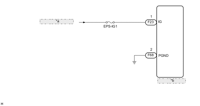
| *a | from IG1-NO. 1 Relay |
| *b | Power Steering ECU Assembly |
CAUTION / NOTICE / HINT
Note
-
If the power steering ECU assembly has been replaced, perform assist map writing and torque sensor zero point calibration.
-
Inspect the fuses for circuits related to this system before performing the following procedure.
PROCEDURE
-
CHECK HARNESS AND CONNECTOR (AUXILIARY BATTERY - POWER STEERING ECU ASSEMBLY)
-
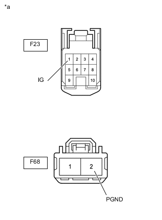
*a Front view of wire harness connector
(to Power Steering ECU Assembly)
Disconnect the F68 and F23 power steering ECU assembly connectors.
-
Measure the voltage according to the value(s) in the table below.
Standard Voltage Tester Connection Condition Specified Condition F23-1 (IG) - Body ground Power switch on (IG) 8 to 16 V -
Measure the resistance according to the value(s) in the table below.
Standard Resistance Tester Connection Condition Specified Condition F68-2 (PGND) - Body ground Always Below 1 Ω Result Result Proceed to OK (for LHD) A OK (for RHD) B NG C
A 
REPLACE POWER STEERING ECU ASSEMBLY Click here
B
REPLACE POWER STEERING ECU ASSEMBLY Click here
C
REPAIR OR REPLACE HARNESS OR CONNECTOR
-