ELECTRIC PARKING BRAKE ECU REMOVAL
CAUTION / NOTICE / HINT
The necessary procedures (adjustment, calibration, initialization, or registration) that must be performed after parts are removed, installed, or replaced during the parking brake ECU assembly removal/installation are shown below.
| Replaced Part or Performed Procedure | Necessary Procedure | Effect/Inoperative Function when Necessary Procedure not Performed | Link |
|---|---|---|---|
| Auxiliary battery terminal is disconnected/reconnected | Memorize steering angle neutral point | Lane departure alert system (w/ Steering Control) | |
| Simple intelligent parking assist system*1 | |||
| Toyota parking assist-sensor system*1 | |||
| Pre-collision system | |||
| Initialize back door lock | Power door lock control system | ||
| Parking brake ECU assembly | Operate the electric parking brake switch | Parking brake indicator light (red) blinks when the power switch is first turned on (IG) |
*1: When performing learning using the GTS.
PROCEDURE
-
PRECAUTION
Note
-
Be sure to read Precaution thoroughly before servicing.
-
After turning the power switch off, waiting time may be required before disconnecting the cable from the negative (-) auxiliary battery terminal. Therefore, make sure to read the disconnecting the cable from the negative (-) auxiliary battery terminal notices before proceeding with work.
-
-
DISCONNECT CABLE FROM NEGATIVE AUXILIARY BATTERY TERMINAL
Note
When disconnecting the cable from the auxiliary negative (-) auxiliary battery terminal, some systems need to be initialized after the cable is reconnected.
-
REMOVE DECK TRIM SIDE PANEL ASSEMBLY LH
-
REMOVE PARKING BRAKE ECU ASSEMBLY
-
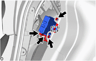
Disconnect the 2 parking brake ECU assembly connectors.
-
Remove the 2 nuts and parking brake ECU assembly.
-