ELECTRIC PARKING BRAKE SYSTEM Electric Parking Brake does not Operate
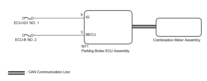
WIRING DIAGRAM
CAUTION / NOTICE / HINT
Note
-
Inspect the fuses for circuits related to this system before performing the following inspection procedure.
-
The electric parking brake may still operate up to 20 seconds after the power switch is turned off. Before disconnecting connectors or fuses, turn the power switch off and wait 20 seconds or more.
-
When replacing the parking brake ECU assembly, operate the electric parking brake switch (electric parking brake switch assembly) as the parking brake indicator light blinks (red) when the power switch is first turned on (IG).
Tech Tips
Even if the electric parking brake is operating normally, the parking brake indicator light (red) on the combination meter may be malfunctioning.
PROCEDURE
-
CHECK CAN COMMUNICATION SYSTEM
-
Check if CAN communication system DTCs are output.
Result Result Proceed to DTCs are not output A DTCs are output B
B 
GO TO CAN COMMUNICATION SYSTEM Click here
A 
-
-
VEHICLE OPERATION CHECK
-
When the vehicle's tires are lifted off the ground and the GTS is used to operate the electric parking brake, check the condition of the rear tires.
Result Result Proceed to Lock and release operation is normal and parking brake indicator light turns off or blinks (red) A Lock and release operation is malfunctioning and parking brake indicator light illuminates (red) or turns off according to switch operation B Lock and release operation is malfunctioning and parking brake indicator light turns off or blinks (red) C
B
INSPECT REAR BRAKE
C 
CHECK HARNESS AND CONNECTOR (BECU CIRCUIT) Click here
A
-
-
PERFORM ACTIVE TEST USING GTS (PARKING BARKE LIGHT)
-
Turn the power switch off.
-
Connect the GTS to the DLC3.
-
Turn the power switch on (IG).
-
Turn the GTS on.
-
Enter the following menus: Chassis / Electric Parking Brake / Active Test.
-
Perform the Active Test according to the display on the GTS.
Chassis > Electric Parking Brake > Active TestTester Display Measurement Item Control Range Diagnostic Note PKB Light Parking brake indicator light (red) ON or OFF
-
Vehicle stopped
-
Power switch on (IG)
-
Parking brake released
Chassis > Electric Parking Brake > Active TestTester Display PKB Light -
-
Select the Data List on the GTS.
Chassis > Electric Parking Brake > Data ListTester Display Measurement Item Range Normal Condition Diagnostic Note Parking Brake Light Parking brake indicator light (red) output signal OFF, Light or Blink OFF: Parking brake indicator light (red) turns off
Light: Parking brake indicator light (red) illuminates
Blink: Parking brake indicator light (red) flashes
-
Chassis > Electric Parking Brake > Data ListTester Display Parking Brake Light -
Check the operating condition of the parking brake indicator light (red) when operating it using the GTS.
Result Result Proceed to Parking brake indicator light (red) in the Data List does not change using the Active Test. A Parking brake indicator light (red) in the Data List turns ON/OFF using the Active Test. B
A
REPLACE PARKING BRAKE ECU ASSEMBLY Click here
B
-
-
INSPECT COMBINATION METER ASSEMBLY
-
Perform the Active Test of the combination meter assembly using the GTS.
Body Electrical > Combination Meter > Active TestTester Display Indicat. Park -
Check the combination meter assembly.
OK Parking brake indicator light (red) turns on or off in accordance with GTS operation. Result Proceed to OK NG
OK
REPLACE PARKING BRAKE ECU ASSEMBLY Click here
NG
GO TO METER / GAUGE SYSTEM Click here
-
-
CHECK HARNESS AND CONNECTOR (BECU CIRCUIT)
-
Turn the power switch off.
-
Disconnect the M71 parking brake ECU assembly connector.
-
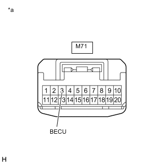
*a Front view of wire harness connector
(to Parking Brake ECU Assembly)
Measure the voltage according to the value(s) in the table below.
Standard Voltage Tester Connection Condition Specified Condition M71-3 (BECU) - Body ground Always 11 to 14 V Result Proceed to OK NG
NG
REPAIR OR REPLACE HARNESS OR CONNECTOR
OK
-
-
CHECK HARNESS AND CONNECTOR (AUXILIARY BATTERY - PARKING BRAKE ECU ASSEMBLY)
-
Turn the power switch off.
-
Disconnect the M71 parking brake ECU assembly connector.
-
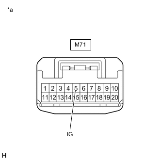
*a Front view of wire harness connector
(to Parking Brake ECU Assembly)
Measure the voltage according to the value(s) in the table below.
Standard Voltage Tester Connection Switch Condition Specified Condition M71-5 (IG) - Body ground Power switch on (IG) 11 to 14 V Result Proceed to OK NG
OK
REPLACE PARKING BRAKE ECU ASSEMBLY Click here
NG
REPAIR OR REPLACE HARNESS OR CONNECTOR
-