ELECTRIC PARKING BRAKE SYSTEM, Diagnostic DTC:C13A1/12
| DTC Code | DTC Name |
|---|---|
| C13A1/12 | Short in Power Supply Relay Circuit |
DESCRIPTION
The following DTCs are stored when a malfunction occurs in the parking brake ECU assembly.
| DTC No. | Detection Item | DTC Detection Condition | Trouble Area | Memory | Note |
|---|---|---|---|---|---|
| C13A1/12 | Short in Power Supply Relay Circuit | Both of following conditions are met:
|
|
DTC stored | An electric parking brake system malfunction is displayed on the multi-information display. |
| Vehicle Condition | |||
|---|---|---|---|
| Pattern 1 | Pattern 2 | ||
| Diagnosis Condition | Power switch on (IG) | ○ | - |
| Electric parking brake switch (electric parking brake switch assembly) pulled to lock side with power switch off | - | ○ | |
| Malfunction Status | Parking brake ECU assembly power source relay is shorted | ○ | ○ |
| Detection Time | Approximately 60 seconds | Approximately 60 seconds | |
| Number of Trips | 1 trip | 1 trip | |
Tech Tips
DTC will be output when conditions for either of the patterns in the table above are met.
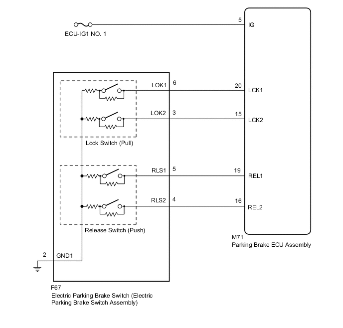
WIRING DIAGRAM
CAUTION / NOTICE / HINT
Note
-
Inspect the fuses for circuits related to this system before performing the following inspection procedure.
-
The electric parking brake may still operate up to 20 seconds after the power switch is turned off. Before disconnecting connectors or fuses, turn the power switch off and wait 20 seconds or more.
-
When replacing the parking brake ECU assembly, operate the electric parking brake switch (electric parking brake switch assembly) as the parking brake indicator light blinks (red) when the power switch is first turned on (IG).
PROCEDURE
-
CHECK HARNESS AND CONNECTOR (PARKING BRAKE ECU ASSEMBLY - IG POWER SOURCE CIRCUIT)
-
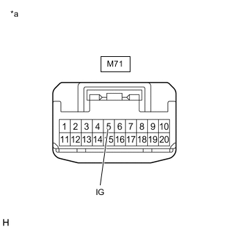
*a Front view of wire harness connector
(to Parking Brake ECU Assembly)
Turn the power switch off.
-
Disconnect the M71 parking brake ECU assembly connector.
-
Measure the voltage according to the value(s) in the table below.
Standard Voltage Tester Connection Switch Condition Specified Condition M71-5 (IG) - Body ground Power switch off Below 2.5 V Result Proceed to OK NG
NG 
REPAIR OR REPLACE HARNESS OR CONNECTOR
OK 
-
-
INSPECT ELECTRIC PARKING BRAKE SWITCH (ELECTRIC PARKING BRAKE SWITCH ASSEMBLY)
-
Inspect the electric parking brake switch (electric parking brake switch assembly).
Result Proceed to OK NG
NG
REPLACE ELECTRIC PARKING BRAKE SWITCH (ELECTRIC PARKING BRAKE SWITCH ASSEMBLY) Click here
OK
-
-
CHECK HARNESS AND CONNECTOR (PARKING BRAKE ECU ASSEMBLY - ELECTRIC PARKING BRAKE SWITCH (ELECTRIC PARKING BRAKE SWITCH ASSEMBLY))
-
Disconnect the F67 electric parking brake switch (electric parking brake switch assembly) connector.
-
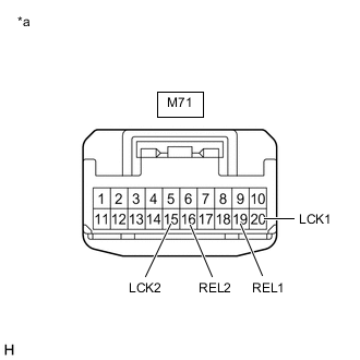
*a Front view of wire harness connector
(to Parking Brake ECU Assembly)
Disconnect the M71 parking brake ECU assembly connector.
-
Measure the resistance according to the value(s) in the table below.
Standard Resistance Tester Connection Condition Specified Condition M71-20 (LCK1) - Body ground Always 10 kΩ or higher M71-15 (LCK2) - Body ground Always 10 kΩ or higher M71-19 (REL1) - Body ground Always 10 kΩ or higher M71-16 (REL2) - Body ground Always 10 kΩ or higher Result Proceed to OK NG
OK
REPLACE PARKING BRAKE ECU ASSEMBLY Click here
NG
REPAIR OR REPLACE HARNESS OR CONNECTOR
-