ELECTRIC PARKING BRAKE SYSTEM, Diagnostic DTC:C13A6/42
| DTC Code | DTC Name |
|---|---|
| C13A6/42 | Open or Short in Circuit of Motor |
DESCRIPTION
| DTC No. | Detection Item | DTC Detection Condition | Trouble Area | Memory | Note |
|---|---|---|---|---|---|
| C13A6/42 | Open or Short in Circuit of Motor | Both of following conditions are met:
|
|
DTC stored | An electric parking brake system malfunction is displayed on the multi-information display. |
| Vehicle Condition | |||
|---|---|---|---|
| Pattern 1 | Pattern 2 | ||
| Diagnosis Condition | Power switch on (IG) | ○ | - |
| Electric parking brake switch (electric parking brake switch assembly) pulled to lock side with power switch off | - | ○ | |
| Malfunction Status | Power supply voltage and +B voltage are normal, but motor circuit is malfunctioning | ○ | ○ |
| Detection Time | Approximately 1 to 2 second | Approximately 1 to 2 second | |
| Number of Trips | 1 trip | 1 trip | |
Tech Tips
DTC will be output when conditions for either of the patterns in the table above are met.
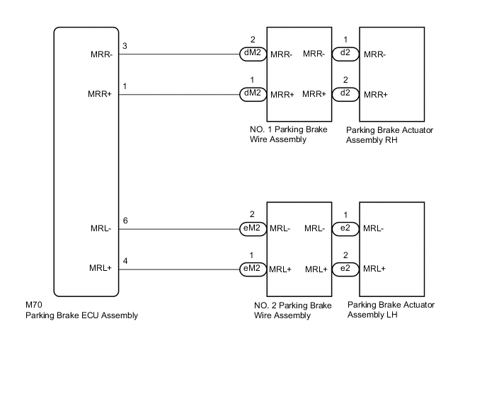
WIRING DIAGRAM
CAUTION / NOTICE / HINT
Note
-
The electric parking brake may still operate up to 20 seconds after the power switch is turned off. Before disconnecting connectors or fuses, turn the power switch off and wait 20 seconds or more.
-
When replacing the parking brake ECU assembly, operate the electric parking brake switch (electric parking brake switch assembly) as the parking brake indicator light blinks (red) when the power switch is first turned on (IG).
PROCEDURE
-
READ VALUE USING GTS (PERMISSION OF RH INTERLOCKING PKB LOCK / PERMISSION OF LH INTERLOCKING PKB LOCK)
-
Turn the power switch off.
-
Connect the GTS to the DLC3.
-
Turn the power switch on (IG).
-
Turn the GTS on.
-
Enter the following menus: Chassis / Electric Parking Brake / Data List.
-
Read the Data List according to the display on the GTS.
Chassis > Electric Parking Brake > Data ListTester Display Measurement Item Range Normal Condition Diagnostic Note Permission of RH Interlocking PKB Lock Parking brake actuator assembly RH parking brake lock control permission status OK or NG OK - Permission of LH Interlocking PKB Lock Parking brake actuator assembly RH parking brake lock control permission status OK or NG OK -
Chassis > Electric Parking Brake > Data ListTester Display Permission of RH Interlocking PKB Lock Permission of LH Interlocking PKB Lock Result Proceed to NEXT
NEXT 
-
-
INSPECT PARKING BRAKE WIRE ASSEMBLY
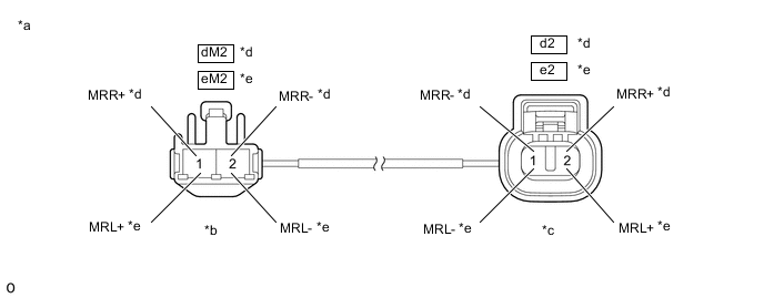
*a Front view of Parking Brake Wire Assembly *b (to wire harness connector) *c (to Parking Brake Actuator Assembly) *d RH *e LH - -
-
Remove the parking brake wire assembly.
-
Check the parking brake wire assembly for damage.
OK No damage. Tech Tips
If damaged, there may be a short in the wire harness or a short to ground.
-
Inspect the parking brake wire assembly.
Standard Resistance RH Tester Connection Condition Specified Condition dM2-2 (MRR-) - d2-1 (MRR-) Always Below 1 Ω dM2-2 (MRR-) - d2-2 (MRR+) Always 10 kΩ or higher dM2-2 (MRR-) or d2-1 (MRR-) - Body ground Always 10 kΩ or higher dM2-1 (MRR+) - d2-2 (MRR+) Always Below 1 Ω dM2-1 (MRR+) - d2-1 (MRR-) Always 10 kΩ or higher dM2-1 (MRR+) or d2-2 (MRR+) - Body ground Always 10 kΩ or higher LH Tester Connection Condition Specified Condition eM2-2 (MRL-) - e2-1 (MRL-) Always Below 1 Ω eM2-2 (MRL-) - e2-2 (MRL+) Always 10 kΩ or higher eM2-2 (MRL-) or e2-1 (MRL-) - Body ground Always 10 kΩ or higher eM2-1 (MRL+) - e2-2 (MRL+) Always Below 1 Ω eM2-1 (MRL+) - e2-1 (MRL-) Always 10 kΩ or higher eM2-1 (MRL+) or e2-2 (MRL+) - Body ground Always 10 kΩ or higher Result Proceed to OK NG
NG 
REPLACE PARKING BRAKE WIRE ASSEMBLY Click here
OK
-
-
CHECK HARNESS AND CONNECTOR (PARKING BRAKE ECU ASSEMBLY - PARKING BRAKE ACTUATOR ASSEMBLY)
-
Turn the power switch off.
-
Make sure the parking brake wire assembly is securely installed.
-
Disconnect the M70 parking brake ECU assembly connector.
-
Disconnect the d2 or e2 parking brake actuator assembly connector.
-
Measure the resistance according to the value(s) in the table below.
Standard Resistance RH Tester Connection Condition Specified Condition M70-1 (MRR+) - d2-2 (MRR+) Always Below 1 Ω M70-3 (MRR-) - d2-1 (MRR-) Always Below 1 Ω M70-1 (MRR+) or d2-2 (MRR+) - Body ground Always 10 kΩ or higher M70-3 (MRR-) or d2-1 (MRR-) - Body ground Always 10 kΩ or higher LH Tester Connection Condition Specified Condition M70-4 (MRL+) - e2-2 (MRL+) Always Below 1 Ω M70-6 (MRL-) - e2-1 (MRL-) Always Below 1 Ω M70-4 (MRL+) or e2-2 (MRL+) - Body ground Always 10 kΩ or higher M70-6 (MRL-) or e2-1 (MRL-) - Body ground Always 10 kΩ or higher Result Proceed to OK NG
NG
REPAIR OR REPLACE HARNESS OR CONNECTOR
OK
-
-
INSPECT PARKING BRAKE ACTUATOR ASSEMBLY
-
Inspect the parking brake actuator assembly.
Result Proceed to OK NG
OK
REPLACE PARKING BRAKE ECU ASSEMBLY Click here
NG
REPLACE PARKING BRAKE ACTUATOR ASSEMBLY Click here
-