ELECTRIC PARKING BRAKE SYSTEM, Diagnostic DTC:C13AD/23
| DTC Code | DTC Name |
|---|---|
| C13AD/23 | Open in +B Circuit |
DESCRIPTION
The parking brake ECU assembly operates the parking brake motor RH and LH with power supplied from the +B and +B2 terminals.
| DTC No. | Detection Item | DTC Detection Condition | Trouble Area | Memory | Note |
|---|---|---|---|---|---|
| C13AD/23 | Open in +B Circuit | All of following conditions are met:
Tech Tips *: When the auxiliary battery voltage is 12 V. |
|
DTC stored | An electric parking brake system malfunction is displayed on the multi-information display. |
| Vehicle Condition | |||||
|---|---|---|---|---|---|
| Pattern 1 | Pattern 2 | Pattern 3 | Pattern 4 | ||
| Diagnosis Condition | Power switch on (IG) | ○ | - | ○ | - |
| Electric parking brake switch (electric parking brake switch assembly) pushed to release side with power switch off | - | ○ | - | ○ | |
| Malfunction Status | When parking brake is not operating: +B voltage is less than 8.5 V* | ○ | ○ | - | - |
| When parking brake is operating: +B voltage is less than 3.5 V* | - | - | ○ | ○ | |
| Detection Time | Approximately 1 second | Approximately 1 second | Approximately 0.5 seconds | Approximately 0.5 seconds | |
| Number of Trips | 1 trip | 1 trip | 1 trip | 1 trip | |
Tech Tips
DTC will be output when conditions for either of the patterns in the table above are met.
-
*: When the auxiliary battery voltage is 12 V.
WIRING DIAGRAM
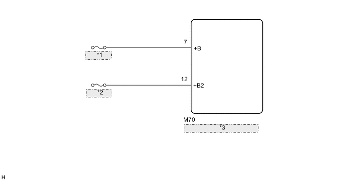
| *1 | EPB NO. 1 |
| *2 | EPB NO. 2 |
| *3 | Parking Brake ECU Assembly |
CAUTION / NOTICE / HINT
Note
-
Inspect the fuses for circuits related to this system before performing the following inspection procedure.
-
The electric parking brake may still operate up to 20 seconds after the power switch is turned off. Before disconnecting connectors or fuses, turn the power switch off and wait 20 seconds or more.
-
When replacing the parking brake ECU assembly, operate the electric parking brake switch (electric parking brake switch assembly) as the parking brake indicator light blinks (red) when the power switch is first turned on (IG).
PROCEDURE
-
READ VALUE USING GTS (ECU +B1 VOLTAGE / ECU +B2 VOLTAGE)
-
Turn the power switch off.
-
Connect the GTS to the DLC3.
-
Turn the power switch on (IG).
-
Turn the GTS on.
-
Enter the following menus: Chassis / Electric Parking Brake / Data List.
-
Check the Data List.
Chassis > Electric Parking Brake > Data ListTester Display Measurement Item Range Normal Condition Diagnostic Note ECU +B1 Voltage Skid control ECU (brake booster with master cylinder assembly) +B1 voltage 0.00 to 20.00 V 11 to 14 V - ECU +B2 Voltage Skid control ECU (brake booster with master cylinder assembly) +B2 voltage 0.00 to 20.00 V 11 to 14 V -
Chassis > Electric Parking Brake > Data ListTester Display ECU +B1 Voltage ECU +B2 Voltage Result Proceed to OK NG
OK 
USE SIMULATION METHOD TO CHECK Click here
NG 
-
-
CHECK HARNESS AND CONNECTOR (PARKING BRAKE ECU ASSEMBLY - AUXILIARY BATTERY)
-
Turn the power switch off.
-
Disconnect the M70 parking brake ECU assembly connector.
-
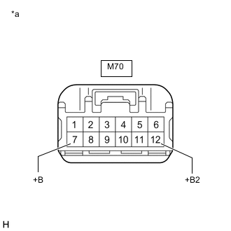
*a Front view of wire harness connector
(to Parking Brake ECU Assembly)
Measure the voltage according to the value(s) in the table below.
Standard Voltage Tester Connection Condition Specified Condition M70-7 (+B) - Body ground Always 11 to 14 V M70-12 (+B2) - Body ground Always 11 to 14 V Result Proceed to OK NG
OK
REPLACE PARKING BRAKE ECU ASSEMBLY Click here
NG
REPAIR OR REPLACE HARNESS OR CONNECTOR
-