FRONT BRAKE INSTALLATION

Info Added 2017-10-06 ![]()
CAUTION / NOTICE / HINT
Note
-
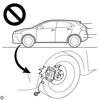
Immediately after installing the brake pads, the braking performance may be reduced. Always perform a road test in a safe place while paying attention to the surroundings.
-
When the brake pedal is first depressed after replacing the brake pads or pushing back the brake caliper piston, DTC C1214 may be stored. As there is no malfunction, clear the DTC.
-
While the auxiliary battery is connected, even if the power switch is off, the brake control system will be activated when the brake pedal is depressed or any door courtesy switch turns on. Therefore, disconnect the auxiliary battery to prevent the brake control system from being activated.
-
After replacing the front disc brake pads, always perform a road test to check the braking performance and check for vibrations.
Tech Tips
-
Use the same procedure for the RH side and LH side.
-
The following procedure is for the LH side.
PROCEDURE
-
INSTALL FRONT DISC
-
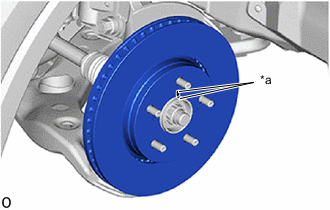
*a Matchmark Align the matchmarks of the front disc and front axle hub sub-assembly, and install the front disc.
Note
When replacing the front disc with a new one, select the installation position where the front disc has minimal runout.
-
-
INSTALL FRONT DISC BRAKE CYLINDER MOUNTING
-
Install the front disc brake cylinder mounting to the steering knuckle with the 2 bolts.
- Torque:
- 107 N*m { 1091 kgf*cm, 79 ft.*lbf }
-
-
INSTALL FRONT DISC BRAKE BUSHING DUST BOOT
-
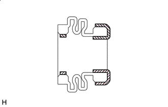

Lithium Soap Base Glycol Grease Apply a light layer of lithium soap base glycol grease to the entire circumference of 2 new front disc brake bushing dust boots.
Tech Tips
Apply more than 0.3 g (0.01 oz) of lithium soap base glycol grease to each front disc brake bushing dust boot.
-
Install the 2 front disc brake bushing dust boots to the front disc brake cylinder mounting.
-
-
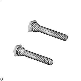
INSTALL FRONT DISC BRAKE CYLINDER SLIDE PIN
-
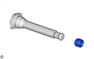
Lithium Soap Base Glycol Grease Apply a light layer of lithium soap base glycol grease to the contact surface of the front disc brake cylinder slide pin (lower side).
-
Install a new front disc brake cylinder slide bushing to the front disc brake cylinder slide pin (lower side).
-
Lithium Soap Base Glycol Grease Apply a light layer of lithium soap base glycol grease to the sliding part and the sealing surfaces of the 2 front disc brake cylinder slide pins.
-
Install the 2 front disc brake cylinder slide pins to the front disc brake cylinder mounting.
-
Push each front disc brake cylinder slide pin into the front disc brake bushing dust boot to engage the pin to the boot.
-
-
INSTALL FRONT DISC BRAKE PAD SUPPORT PLATE
-
Install the 4 front disc brake pad support plates to the front disc brake cylinder mounting.
Note
-
Be sure to install each front disc brake pad support plate in the correct position and direction.
-
When reusing the brake pad support plates, use the identification marks created during removal to install them to the original positions.
-
-
-
INSTALL FRONT DISC BRAKE ANTI-SQUEAL SHIM KIT
-
INSTALL FRONT DISC BRAKE PAD
-
Install the 2 front disc brake pads to the front disc brake cylinder mounting.
-
-
INSTALL FRONT DISC BRAKE CYLINDER ASSEMBLY
-
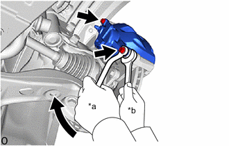
*a Turn *b Hold Hold each front disc brake cylinder slide pin and install the front disc brake cylinder assembly to the front disc brake cylinder mounting with 2 new bolts.
- Torque:
- 31.5 N*m { 321 kgf*cm, 23 ft.*lbf }
CAUTION:
-
Do not reuse the bolts.
-
If the bolts are reused, the front disc brake cylinder assembly could come off, which could cause an accident.
-
-
CONNECT FRONT FLEXIBLE HOSE
-
Connect the front flexible hose to the front disc brake cylinder assembly with a new union bolt and a new gasket.
- Torque:
- 29 N*m { 296 kgf*cm, 21 ft.*lbf }
Note
Install the front flexible hose lock securely into the lock hole in the front disc brake cylinder assembly.
-
-
CONNECT CABLE TO NEGATIVE AUXILIARY BATTERY TERMINAL
-
Connect the reservoir level switch connector.
-
Connect the cable to the negative (-) auxiliary battery terminal.
-
Perform the following procedure if air bleeding is not necessary:
-
Turn the power switch on (READY).
-
Depress the brake pedal and release it.
-
Clear the DTCs.
-
-
-
BLEED BRAKE LINE
-
INSTALL FRONT WHEEL