BRAKE ACTUATOR(for RHD) REMOVAL
CAUTION / NOTICE / HINT
The necessary procedures (adjustment, calibration, initialization, or registration) that must be performed after parts are removed and installed, or replaced during engine assembly removal/installation are shown below.
| Replaced Part or Performed Procedure | Necessary Procedure | Effect/Inoperative Function when Necessary Procedure not Performed | Link |
|---|---|---|---|
| Disconnect cable from negative auxiliary battery terminal | Memorize steering angle neutral point | Lane departure alert system (w/ Steering Control) | |
| Simple intelligent parking assist system*1 | |||
| Toyota parking assist-sensor system*1 | |||
| Pre-collision system | |||
| Initialize back door lock | Power door lock control system | ||
| Replacement of brake actuator assembly |
|
|
for Initialization: Click here for Calibration: Click here |
| Replacement of inverter with converter assembly | Resolver learning |
|
|
for SFI system |
Perform Vehicle Identification Number (VIN) or frame number registration | ||
for SFI system |
Inspection After Repair |
|
|
| Suspension, tires, etc. (The vehicle height changes because of suspension or tire replacement) |
Initialize No. 1 headlight ECU sub-assembly LH | Automatic headlight beam level control system | |
| Front wheel alignment adjustment |
|
|
|
| Replacement of hybrid vehicle transaxle assembly |
|
|
*1: When performing learning using the GTS.
CAUTION:
-
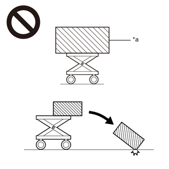
*a An Object Exceeding Weight Limit of Engine Lifter The engine assembly with transaxle is very heavy. Be sure to follow the procedure described in the repair manual, or the engine lifter may suddenly drop or the engine assembly with transaxle may fall off the engine lifter.
-
To prevent burns, do not touch the engine, exhaust manifold or other high temperature components while the engine is hot.
Note
While the auxiliary battery is connected, even if the power switch is off, the brake control system activates when the brake pedal is depressed or any door courtesy switch turns on. Therefore, when servicing the brake system components, do not operate the brake pedal or open/close the doors while the auxiliary battery is connected.
PROCEDURE
-
REMOVE BRAKE BOOSTER PUMP ASSEMBLY
-
REMOVE BRAKE ACTUATOR ASSEMBLY
-
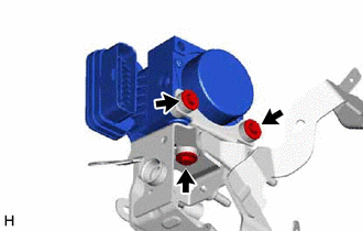
Remove the 3 bolts and brake actuator assembly from the brake actuator bracket assembly.
Note
-
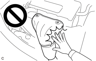
Do not hold the brake actuator assembly by the connector.
-
Do not drop the brake actuator assembly when carrying it.
-
-