ELECTRONICALLY CONTROLLED BRAKE SYSTEM, Diagnostic DTC:C146C, C146D
| DTC Code | DTC Name |
|---|---|
| C146C | Open Circuit in ABS Motor Relay Circuit |
| C146D | Short Circuit in ABS Motor Relay Circuit |
DESCRIPTION
The ABS motor relay is built into the brake booster with master cylinder assembly.
During ABS, TRC, VSC or brake assist operation, the skid control ECU (brake booster with master cylinder assembly) turns on the ABS motor relay to run the pump motor in the brake actuator assembly.
When any DTC related to the ABS motor is stored, the IC built into the skid control ECU (brake booster with master cylinder assembly) operates in fail-safe mode.
When the supplied voltage to the BM terminal of the ABS motor relay is excessively low due to an auxiliary battery or charging circuit malfunction, DTC C146C and/or C146D is stored.
| DTC No. | Detection Item | INF Code | DTC Detection Condition | Trouble Area | Note |
|---|---|---|---|---|---|
| C146C | Open Circuit in ABS Motor Relay Circuit | 612 | When operation of the ABS motor is requested, the ABS motor voltage is less than 7.6 V for 0.2 seconds or more. |
|
ABS DTC |
| C146D | Short Circuit in ABS Motor Relay Circuit | 613 | A short in the ABS motor relay drive circuit is detected for 4 seconds or more. |
|
ABS DTC |
CAUTION / NOTICE / HINT
Note
-
After replacing the skid control ECU (brake booster with master cylinder assembly), perform linear solenoid valve offset learning, ABS holding solenoid valve learning, yaw rate and acceleration sensor zero point calibration and system information memorization after performing "Reset Memory".
-
Inspect the fuses for circuits related to this system before performing the following procedure.
Tech Tips
When DTCs C1241 and/or C1417 are output together with C146C and/or C146D, inspect and repair the trouble areas indicated by C1241 and/or C1417 first.
for C1241: Click here
for C1417: Click here
PROCEDURE
-
CHECK HARNESS AND CONNECTOR (BM TERMINAL)
-
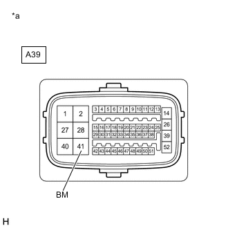
*a Front view of wire harness connector
(to Skid Control ECU (Brake Booster with Master Cylinder Assembly))
Make sure that there is no looseness at the locking part and the connecting part of the connector.
OK The connector is securely connected. -
Disconnect the A39 skid control ECU (brake booster with master cylinder assembly) connector.
-
Check both the connector case and the terminals for deformation and corrosion.
OK No deformation or corrosion. -
Measure the voltage according to the value(s) in the table below.
Standard Voltage Tester Connection Condition Specified Condition A39-41 (BM) - Body ground Always 11 to 14 V Result Proceed to OK NG
NG 
REPAIR OR REPLACE HARNESS OR CONNECTOR (BM CIRCUIT)
OK 
-
-
CHECK HARNESS AND CONNECTOR (BRAKE BOOSTER WITH MASTER CYLINDER ASSEMBLY - BRAKE ACTUATOR ASSEMBLY)
-
Make sure that there is no looseness at the locking part and the connecting part of the connector.
OK The connector is securely connected. -
Disconnect the A40 brake actuator assembly connector (for LHD).
-
Disconnect the A41 brake actuator assembly connector (for RHD).
-
Check both the connector case and the terminals for deformation and corrosion.
OK No deformation or corrosion. -
Measure the resistance according to the value(s) in the table below.
Standard Resistance for LHD Tester Connection Condition Specified Condition A39-40 (+BM) - A40-13 (+BM) Always Below 1 Ω A39-40 (+BM) or A40-13 (+BM) - Body ground Always 10 kΩ or higher for RHD Tester Connection Condition Specified Condition A39-40 (+BM) - A41-13 (+BM) Always Below 1 Ω A39-40 (+BM) or A41-13 (+BM) - Body ground Always 10 kΩ or higher Result Proceed to OK NG
NG
REPAIR OR REPLACE HARNESS OR CONNECTOR
OK
-
-
CHECK HARNESS AND CONNECTOR (GND TERMINAL)
-
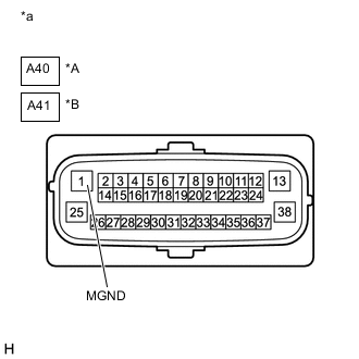
*A for LHD *B for RHD *a Front view of wire harness connector
(to Brake Actuator Assembly)
Measure the resistance according to the value(s) in the table below.
Standard Resistance for LHD Tester Connection Condition Specified Condition A40-1 (MGND) - Body ground Always Below 1 Ω for RHD Tester Connection Condition Specified Condition A41-1 (MGND) - Body ground Always Below 1 Ω Result Proceed to OK NG
NG
REPAIR OR REPLACE HARNESS OR CONNECTOR (GND CIRCUIT)
OK
-
-
RECONFIRM DTC
-
Reconnect the A39 skid control ECU (brake booster with master cylinder assembly) connector.
-
Reconnect the A40 brake actuator assembly connector (for LHD).
-
Reconnect the A41 brake actuator assembly connector (for RHD).
-
Clear the DTCs.
Chassis > ABS/VSC/TRC > Clear DTCs -
Turn the power switch off.
-
Turn the power switch on (READY).
-
Perform a road test.
-
Check if the same DTC is output.
Chassis > ABS/VSC/TRC > Trouble CodesResult Result Proceed to DTCs C146C and C146D are not output. A DTCs C146C and/or C146D are output. (for LHD) B DTCs C146C and/or C146D are output. (for RHD) C Tech Tips
-
If a speed signal of 20 km/h (12 mph) or more is sent to the skid control ECU (brake booster with master cylinder assembly) with the power switch on (IG) and the stop light switch assembly off, the ECU performs self diagnosis of the motor and solenoid circuits.
-
If the normal system code is output (no DTCs are output), slightly jiggle the connectors, wire harness, and fuses of the skid control ECU (brake booster with master cylinder assembly).
-
If any DTCs are output while jiggling a connector or wire harness from the skid control ECU (brake booster with master cylinder assembly), inspect and repair the connector or wire harness.
-
The DTCs were probably output due to a bad connection of the connector terminal.
-
A
USE SIMULATION METHOD TO CHECK Click here
B
REPLACE BRAKE BOOSTER WITH MASTER CYLINDER ASSEMBLY Click here
C
REPLACE BRAKE BOOSTER WITH MASTER CYLINDER ASSEMBLY Click here
-