ELECTRONICALLY CONTROLLED BRAKE SYSTEM, Diagnostic DTC:C1380
| DTC Code | DTC Name |
|---|---|
| C1380 | Stop Light Control Relay Malfunction |
DESCRIPTION
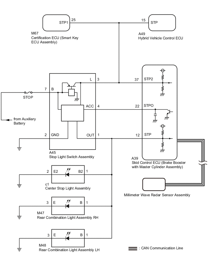
Upon receiving the dynamic radar cruise control or brake hold control operating signal from the skid control ECU (brake booster with master cylinder assembly), the relay contact turns on and the stop lights come on.
| DTC No. | Detection Item | INF Code | DTC Detection Condition | Trouble Area | Note |
|---|---|---|---|---|---|
| C1380 | Stop Light Control Relay Malfunction | 761 762 |
|
|
VSC DTC |
WIRING DIAGRAM
CAUTION / NOTICE / HINT
Note
-
After replacing the skid control ECU (brake booster with master cylinder assembly), perform linear solenoid valve offset learning, ABS holding solenoid valve learning, yaw rate and acceleration sensor zero point calibration and system information memorization after performing "Reset Memory".
-
Inspect the fuses for circuits related to this system before performing the following procedure.
-
Before replacing the certification ECU (smart key ECU assembly), refer to Service Bulletin.
PROCEDURE
-
CHECK HARNESS AND CONNECTOR (STP, STPO AND STP2 TERMINAL)
-
Turn the power switch off.
-
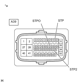
*a Front view of wire harness connector
(to Skid Control ECU (Brake Booster with Master Cylinder Assembly))
Disconnect the skid control ECU (brake booster with master cylinder assembly) connector.
-
Measure the voltage according to the value(s) in the table below.
Standard Voltage Tester Connection Condition Specified Condition A39-12 (STP) - Body ground Brake pedal depressed 11 to 14 V Brake pedal released Below 1.5 V A39-22 (STPO) - Body ground Always 11 to 14 V A39-37 (STP2) - Body ground Brake pedal depressed 11 to 14 V Brake pedal released Below 1.5 V Result Result Proceed to All terminal voltage is normal A Only STP2 terminal voltage abnormal B Only STPO terminal voltage abnormal C Only STP terminal voltage abnormal D STPO terminal and STP2 terminal voltage abnormal E
B 
CHECK HARNESS AND CONNECTOR (BRAKE BOOSTER WITH MASTER CYLINDER ASSEMBLY - HYBRID VEHICLE CONTROL ECU) Click here
C
CHECK HARNESS AND CONNECTOR (BRAKE BOOSTER WITH MASTER CYLINDER ASSEMBLY - STOP LIGHT SWITCH ASSEMBLY) Click here
D
CHECK HARNESS AND CONNECTOR (BRAKE BOOSTER WITH MASTER CYLINDER ASSEMBLY - REAR COMBINATION LIGHT ASSEMBLY LH) Click here
E
CHECK STOP LIGHT SWITCH ASSEMBLY POWER SOURCE CIRCUIT Click here
A 
-
-
PERFORM ACTIVE TEST USING GTS (STOP LIGHT RELAY)
-
Enter the following menus: Chassis / ABS/VSC/TRC / Active Test.
-
Perform "Active Test" according to the display on the GTS.
Chassis > ABS/VSC/TRC > Active TestTester Display Measurement Item Control Range Diagnostic Note Stop Light Relay Stop light control relay (Stop light switch assembly) ON or OFF Stop lights come on
Chassis > ABS/VSC/TRC > Active TestTester Display Stop Light Relay OK Stop light turns ON/OFF in response to the GTS operation Result Proceed to OK NG
NG
INSPECT BRAKE BOOSTER WITH MASTER CYLINDER ASSEMBLY Click here
OK
-
-
CHECK FOR DTC
-
Clear the DTCs.
Chassis > ABS/VSC/TRC > Clear DTCs -
Enter the following menus: Chassis / ABS/VSC/TRC / Active Test.
-
Perform "Active Test" according to the display on the GTS.
Chassis > ABS/VSC/TRC > Active TestTester Display Measurement Item Control Range Diagnostic Note Stop Light Relay Stop light control relay (Stop light switch assembly) ON or OFF Stop lights come on
Chassis > ABS/VSC/TRC > Active TestTester Display Stop Light Relay -
Check for DTCs.
Chassis > ABS/VSC/TRC > Clear DTCsResult Result Proceed to DTC C1380 is output (for LHD) A DTC C1380 is output (for RHD) B DTC C1380 is not output C
A 
REPLACE BRAKE BOOSTER WITH MASTER CYLINDER ASSEMBLY Click here
B
REPLACE BRAKE BOOSTER WITH MASTER CYLINDER ASSEMBLY Click here
C
USE SIMULATION METHOD TO CHECK Click here
-
-
INSPECT BRAKE BOOSTER WITH MASTER CYLINDER ASSEMBLY
-
Enter the following menus: Chassis / ABS/VSC/TRC / Active Test.
-
Perform "Active Test" according to the display on the GTS.
Chassis > ABS/VSC/TRC > Active TestTester Display Measurement Item Control Range Diagnostic Note Stop Light Relay Stop light control relay (Stop light switch assembly) ON or OFF Stop lights come on
Chassis > ABS/VSC/TRC > Active TestTester Display Stop Light Relay -
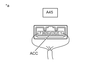
*a Component with harness connected
(Stop Light Switch Assembly)
Measure the voltage according to the value(s) in the table below.
Standard Voltage Tester Connection Condition Specified Condition A45-4 (ACC) - Body ground Active Test is ON Below 1.5 V Result Result Proceed to OK A NG (for LHD) B NG (for RHD) C
A
REPLACE STOP LIGHT SWITCH ASSEMBLY Click here
B
REPLACE BRAKE BOOSTER WITH MASTER CYLINDER ASSEMBLY Click here
C
REPLACE BRAKE BOOSTER WITH MASTER CYLINDER ASSEMBLY Click here
-
-
CHECK HARNESS AND CONNECTOR (BRAKE BOOSTER WITH MASTER CYLINDER ASSEMBLY - HYBRID VEHICLE CONTROL ECU)
-
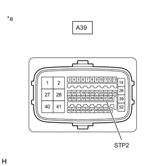
*a Front view of wire harness connector
(to Skid Control ECU (Brake Booster with Master Cylinder Assembly))
Make sure that there is no looseness at the locking part and the connecting part of the connector.
OK The connector is securely connected. -
Disconnect the A49 hybrid vehicle control ECU connector.
-
Check both the connector case and the terminals for deformation and corrosion.
OK No deformation or corrosion. -
Measure the voltage according to the value(s) in the table below.
Standard Voltage Tester Connection Condition Specified Condition A39-37 (STP2) - Body ground Stop light switch assembly on (Brake pedal depressed) 11 to 14 V A39-37 (STP2) - Body ground Stop light switch assembly off (Brake pedal released) Below 1.5 V Result Proceed to OK NG
OK
REPLACE HYBRID VEHICLE CONTROL ECU Click here
NG
-
-
CHECK HARNESS AND CONNECTOR (BRAKE BOOSTER WITH MASTER CYLINDER ASSEMBLY - SMART KEY ECU ASSEMBLY)
-
*a Front view of wire harness connector
(to Skid Control ECU (Brake Booster with Master Cylinder Assembly))
Make sure that there is no looseness at the locking part and the connecting part of the connector.
OK The connector is securely connected. -
Disconnect the M67 certification ECU (smart key ECU assembly) connector.
-
Check both the connector case and the terminals for deformation and corrosion.
OK No deformation or corrosion. -
Measure the voltage according to the value(s) in the table below.
Standard Voltage Tester Connection Condition Specified Condition A39-37 (STP2) - Body ground Stop light switch assembly on (Brake pedal depressed) 11 to 14 V A39-37 (STP2) - Body ground Stop light switch assembly off (Brake pedal released) Below 1.5 V Result Proceed to OK NG
OK
REPLACE SMART KEY ECU ASSEMBLY
NG
-
-
CHECK HARNESS AND CONNECTOR (BRAKE BOOSTER WITH MASTER CYLINDER ASSEMBLY - STOP LIGHT SWITCH ASSEMBLY)
-
*a Front view of wire harness connector
(to Skid Control ECU (Brake Booster with Master Cylinder Assembly))
Make sure that there is no looseness at the locking part and the connecting part of the connector.
OK The connector is securely connected. -
Disconnect the A45 stop light switch assembly connector.
-
Check both the connector case and the terminals for deformation and corrosion.
OK No deformation or corrosion. -
Measure the voltage according to the value(s) in the table below.
Standard Voltage Tester Connection Condition Specified Condition A39-37 (STP2) - Body ground Always Below 1.5 V Result Proceed to OK NG
NG
REPAIR OR REPLACE HARNESS OR CONNECTOR
OK
-
-
CHECK HARNESS AND CONNECTOR (BRAKE BOOSTER WITH MASTER CYLINDER ASSEMBLY - STOP LIGHT SWITCH ASSEMBLY)
-
Turn the power switch off.
-
Disconnect the A39 skid control ECU (brake booster with master cylinder assembly) connector.
-
Disconnect the A45 stop light switch assembly connector.
-
Measure the resistance according to the value(s) in the table below.
Standard Resistance Tester Connection Condition Specified Condition A39-37 (STP2) - A45-3 (L) Always Below 1 Ω A39-37 (STP2) or A45-3 (L) - Body ground Always 10 kΩ or higher Result Proceed to OK NG
OK
REPLACE STOP LIGHT SWITCH ASSEMBLY Click here
NG
REPAIR OR REPLACE HARNESS OR CONNECTOR
-
-
CHECK HARNESS AND CONNECTOR (BRAKE BOOSTER WITH MASTER CYLINDER ASSEMBLY - STOP LIGHT SWITCH ASSEMBLY)
-
Turn the power switch off.
-
Disconnect the A39 skid control ECU (brake booster with master cylinder assembly) connector.
-
Disconnect the A45 stop light switch assembly connector.
-
Measure the resistance according to the value(s) in the table below.
Standard Resistance Tester Connection Condition Specified Condition A39-22 (STPO) - A45-4 (ACC) Always Below 1 Ω Result Proceed to OK NG
OK
REPLACE STOP LIGHT SWITCH ASSEMBLY Click here
NG
REPAIR OR REPLACE HARNESS OR CONNECTOR
-
-
CHECK HARNESS AND CONNECTOR (BRAKE BOOSTER WITH MASTER CYLINDER ASSEMBLY - REAR COMBINATION LIGHT ASSEMBLY LH)
-
Turn the power switch off.
-
Disconnect the A39 skid control ECU (brake booster with master cylinder assembly) connector.
-
Disconnect the M48 rear combination light assembly LH connector.
-
Measure the voltage according to the value(s) in the table below.
Standard Voltage Tester Connection Condition Specified Condition A39-12 (STP) - Body ground Brake pedal depressed 11 to 14 V A39-12 (STP) - Body ground Brake pedal released Below 1.5 V Result Proceed to OK NG
OK
REPLACE REAR COMBINATION LIGHT ASSEMBLY LH for LED Type: Click here
REPLACE REAR COMBINATION LIGHT ASSEMBLY LH for Bulb Type: Click hereNG
-
-
CHECK HARNESS AND CONNECTOR (BRAKE BOOSTER WITH MASTER CYLINDER ASSEMBLY - REAR COMBINATION LIGHT ASSEMBLY RH)
-
Turn the power switch off.
-
Disconnect the A39 skid control ECU (brake booster with master cylinder assembly) connector.
-
Disconnect the M48 rear combination light assembly LH connector.
-
Disconnect the M47 rear combination light assembly RH connector.
-
Measure the voltage according to the value(s) in the table below.
Standard Voltage Tester Connection Condition Specified Condition A39-12 (STP) - Body ground Brake pedal depressed 11 to 14 V A39-12 (STP) - Body ground Brake pedal released Below 1.5 V Result Proceed to OK NG
OK
REPLACE REAR COMBINATION LIGHT ASSEMBLY RH for LED Type: Click here
REPLACE REAR COMBINATION LIGHT ASSEMBLY RH for Bulb Type: Click hereNG
-
-
CHECK HARNESS AND CONNECTOR (BRAKE BOOSTER WITH MASTER CYLINDER ASSEMBLY - CENTER STOP LIGHT ASSEMBLY)
-
Turn the power switch off.
-
Disconnect the A39 skid control ECU (brake booster with master cylinder assembly) connector.
-
Disconnect the M48 rear combination light assembly LH connector.
-
Disconnect the M47 rear combination light assembly RH connector.
-
Disconnect the c1 center stop light assembly connector.
-
Measure the voltage according to the value(s) in the table below.
Standard Voltage Tester Connection Condition Specified Condition A39-12 (STP) - Body ground Brake pedal depressed 11 to 14 V A39-12 (STP) - Body ground Brake pedal released Below 1.5 V Result Proceed to OK NG
OK
REPLACE CENTER STOP LIGHT ASSEMBLY Click here
NG
-
-
CHECK HARNESS AND CONNECTOR (BRAKE BOOSTER WITH MASTER CYLINDER ASSEMBLY - STOP LIGHT SWITCH ASSEMBLY)
-
Turn the power switch off.
-
Disconnect the A39 skid control ECU (brake booster with master cylinder assembly) connector.
-
Disconnect the M48 rear combination light assembly LH connector.
-
Disconnect the M47 rear combination light assembly RH connector.
-
Disconnect the c1 center stop light assembly connector.
-
Disconnect the A45 stop light switch assembly connector.
-
Measure the resistance according to the value(s) in the table below.
Standard Resistance Tester Connection Condition Specified Condition A45-1 (OUT) - A39-12 (STP) Always Below 1 Ω A45-1 (OUT) or A39-12 (STP) - Body ground Always 10 kΩ or higher Result Proceed to OK NG
OK
REPLACE STOP LIGHT SWITCH ASSEMBLY Click here
NG
REPAIR OR REPLACE HARNESS OR CONNECTOR
-
-
CHECK STOP LIGHT SWITCH ASSEMBLY POWER SOURCE CIRCUIT
-
Turn the power switch off.
-
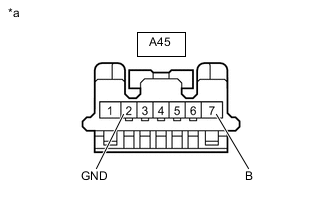
*a Front view of wire harness connector
(to Stop Light Switch Assembly)
Disconnect the stop light switch assembly connector.
-
Measure the resistance according to the value(s) in the table below.
Standard Resistance Tester Connection Condition Specified Condition A45-2 (GND) - Body ground Always Below 1 Ω -
Measure the voltage according to the value(s) in the table below.
Standard Voltage Tester Connection Condition Specified Condition A45-7 (B) - Body ground Always 11 to 14 V Result Proceed to OK NG
NG
REPAIR OR REPLACE HARNESS OR CONNECTOR
OK
-
-
CHECK HARNESS AND CONNECTOR (BRAKE BOOSTER WITH MASTER CYLINDER ASSEMBLY - STOP LIGHT SWITCH ASSEMBLY)
-
Turn the power switch off.
-
Disconnect the A39 skid control ECU (brake booster with master cylinder assembly) connector.
-
Disconnect the A45 stop light switch assembly connector.
-
Measure the resistance according to the value(s) in the table below.
Standard Resistance Tester Connection Condition Specified Condition A39-22 (STPO) - A45-4 (ACC) Always Below 1 Ω Result Proceed to OK NG
OK
REPLACE STOP LIGHT SWITCH ASSEMBLY Click here
NG
REPAIR OR REPLACE HARNESS OR CONNECTOR
-