STEERING KNUCKLE REMOVAL
CAUTION / NOTICE / HINT
The necessary procedures (adjustment, calibration, initialization, or registration) that must be performed after parts are removed and installed, or replaced during steering knuckle removal/installation are shown below.
| Replaced Part or Performed Procedure | Necessary Procedure | Effect/Inoperative Function when Necessary Procedure not Performed | Link |
|---|---|---|---|
| Front wheel alignment adjustment |
|
|
for Initialization: Click here for Calibration: Click here |
| Auxiliary battery terminal is disconnected/reconnected | Memorize steering angle neutral point |
|
|
| Initialize back door lock | Power door lock control system |
-
*1: When performing learning using the GTS.
Note
-
When removing or installing the front disc brake caliper assembly, pushing back the disc brake piston may cause a large clearance between the brake pads and brake disc. When the brake pedal is depressed with a large clearance between the brake pads and the brake disc, DTC C1214 related to abnormal brake fluid pressure may be stored. Make sure to clear any DTCs after performing this step.
-
While the auxiliary battery is connected, even if the power switch is off, the brake control system activates when the brake pedal is depressed or any door courtesy switch turns on. Therefore, when servicing the brake system components, do not operate the brake pedal or open/close the doors while the auxiliary battery is connected.
Tech Tips
-
Use the same procedure for the RH side and LH side.
-
The following procedure is for the LH side.
PROCEDURE
-
REMOVE FRONT AXLE ASSEMBLY
-
REMOVE FRONT LOWER BALL JOINT ASSEMBLY
-
REMOVE STEERING KNUCKLE
-
Secure the front axle assembly between aluminum plates in a vise.
Note
Do not overtighten the vise.
-
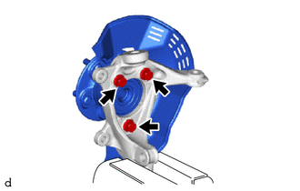
Remove the 3 bolts, front axle hub sub-assembly and front disc brake dust cover from the steering knuckle.
Note
-
Do not drop the front axle hub sub-assembly.
-
Be careful not to damage the speed sensor rotor or contact surfaces.
-
Do not allow foreign matter to contact the speed sensor rotor or contact surfaces.
-
-