SHIFT LEVER POSITION SENSOR INSTALLATION

PROCEDURE
-
INSTALL SHIFT LEVER POSITION SENSOR SEAL
Tech Tips
Perform this procedure only when replacement of the shift lever position sensor seal is necessary.
-
Coat the lip of a new shift lever position sensor seal with MP grease.
-
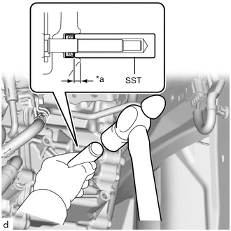
*a Depth Using SST and a hammer, install the shift lever position sensor seal to the hybrid vehicle transaxle assembly.
- SST
- 09350-30020 ( 09350-07110 )
Standard Depth 4.05 to 5.40 mm (0.159 to 0.213 in.) Note
-
Be sure to install the shift lever position sensor seal in the correct direction.
-
Do not install the shift lever position sensor seal at an angle.
-
-
INSTALL SHIFT LEVER POSITION SENSOR
-
Temporarily install the shift lever position sensor to the hybrid vehicle transaxle assembly with the 2 bolts.
Note
-
Do not reuse the shift lever position sensor if it has been dropped or subjected to a severe impact.
-
Do not allow moisture to adhere to the connector terminal.
-
-
Install the lock nut and lock plate to the shift lever position sensor.
- Torque:
- 6.9 N*m { 70 kgf*cm, 61 in.*lbf }
-
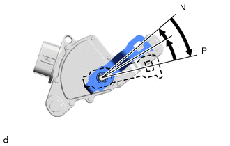
Temporarily install the control shaft lever.
-
Turn the control shaft lever clockwise until it stops, and then from that position turn it counterclockwise by 2 notches to set it to the N position.
-
Remove the control shaft lever.
-
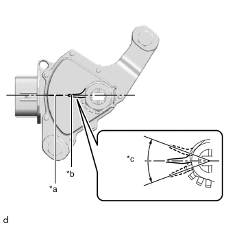
*a Neutral Basic Line *b Protrusion *c Range of Play Align the protrusion with the neutral basic line.
Note
The protrusion of the lock plate has a certain amount of play. Align the center point of the range of play with the neutral basic line.
-
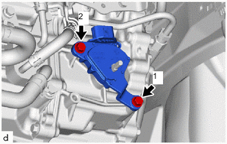
Tighten the 2 bolts in the order shown in the illustration.
- Torque:
- 11 N*m { 112 kgf*cm, 8 ft.*lbf }
-
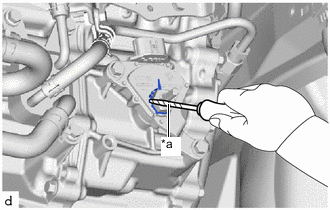
*a Protective Tape Using a screwdriver with its tip wrapped in protective tape, bend down the tabs of the lock plate.
-
Install the control shaft lever to the hybrid vehicle transaxle assembly with the nut and washer.
- Torque:
- 12.7 N*m { 130 kgf*cm, 9 ft.*lbf }
-
Connect the shift lever position sensor connector.
-
-
CONNECT TRANSMISSION CONTROL CABLE ASSEMBLY
-
Connect the transmission control cable assembly to the No. 1 transmission control cable bracket with a new clip.
-
Connect the transmission control cable assembly to the control shaft lever with the nut.
- Torque:
- 12 N*m { 122 kgf*cm, 9 ft.*lbf }
Note
Before connecting the transmission control cable assembly, check that the shift lever position sensor and shift lever are in neutral.
-
-
INSPECT SHIFT LEVER POSITION
-
ADJUST SHIFT LEVER POSITION
-
INSPECT SHIFT LEVER POSITION SENSOR POSITION
-
ADJUST SHIFT LEVER POSITION SENSOR POSITION
-
INSTALL REAR ENGINE UNDER COVER LH
-
INSTALL NO. 1 ENGINE UNDER COVER