INTAKE MANIFOLD INSTALLATION
Info Added 2017-10-06 ![]()
PROCEDURE
-
INSTALL STUD BOLT (w/ Stud Bolt)
Tech Tips
If a stud bolt is deformed or the threads are damaged, replace it.
-
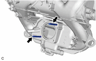
Using an E6 "TORX" socket wrench, install the 2 stud bolts to the intake manifold.
- Torque:
- 5.0 N*m { 51 kgf*cm, 44 in.*lbf }
-
-
INSTALL NO. 1 INTAKE MANIFOLD TO HEAD GASKET
-
Install a new No. 1 intake manifold to head gasket to the intake manifold.
-
-
INSTALL INTAKE MANIFOLD
-
Temporarily install the intake manifold to the cylinder head sub-assembly with the 3 bolts and 2 nuts.
-
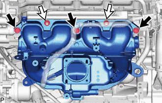

Bolt 
Nut Tighten the 3 bolts and 2 nuts in several steps.
- Torque:
- 28 N*m { 286 kgf*cm, 21 ft.*lbf }
-
-
CONNECT WATER BY-PASS HOSE
-
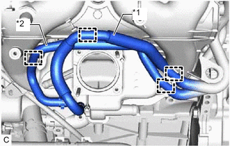
*1 Water By-Pass Hose *2 No. 2 Water By-pass Hose Engage the 2 hose clamps to connect the No. 2 water by-pass hose to the intake manifold.
-
Engage the 2 hose clamps to connect the water by-pass hose to the intake manifold.
-
-
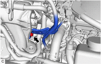
CONNECT NO. 2 FUEL VAPOR FEED HOSE
-
Connect the No. 2 fuel vapor feed hose to the intake manifold.
-
Engage the 2 hose clamps to connect the No. 2 fuel vapor feed hose to the intake manifold.
-
-
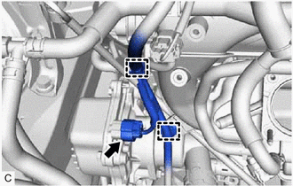
CONNECT NO. 8 WATER BY-PASS HOSE
-
Connect the No. 8 water by-pass hose to the No. 3 water by-pass pipe and slide the clip to secure it.
-
Engage the 2 hose clamps.
-
-
CONNECT ENGINE COVER BRACKET
-
Connect the engine cover bracket to the intake manifold with the bolt.
- Torque:
- 10 N*m { 102 kgf*cm, 7 ft.*lbf }
-
-
CONNECT ENGINE WIRE
-
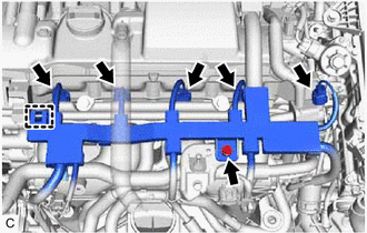
Engage the clamp and connect the engine wire with the bolt.
- Torque:
- 8.0 N*m { 82 kgf*cm, 71 in.*lbf }
-
Connect the 4 fuel injector assembly connectors and purge valve (purge VSV) connector.
-
Connect the wire harness bracket with the bolt.
- Torque:
- 8.0 N*m { 82 kgf*cm, 71 in.*lbf }
-
Connect the engine water pump assembly connector.
-
Engage the 2 clamps.
-
-
CONNECT VENTILATION HOSE
-
Connect the ventilation hose to the intake manifold and slide the clip to secure it.
-
-
INSTALL E.F.I. VACUUM SENSOR ASSEMBLY (MANIFOLD ABSOLUTE PRESSURE SENSOR)
-
Install the E.F.I. vacuum sensor assembly (manifold absolute pressure sensor) to the intake manifold with the bolt.
- Torque:
- 7.0 N*m { 71 kgf*cm, 62 in.*lbf }
-
Connect the vacuum hose to the intake manifold.
-
Connect the E.F.I. vacuum sensor assembly (manifold absolute pressure sensor) connector.
-
-
INSTALL EGR PIPE ASSEMBLY
-
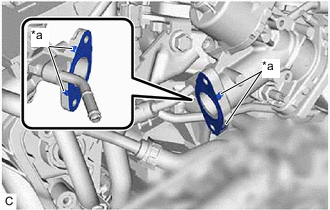
*a Claw Install a new EGR pipe gasket to the EGR valve assembly.
Note
Make sure that the claws of the EGR valve gasket are toward the EGR valve assembly side.
-
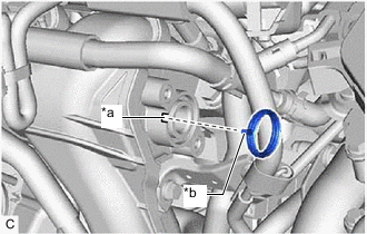
*a Groove *b Protrusion Install a new inlet EGR gasket to the intake manifold.
Tech Tips
Align the protrusion of the inlet EGR gasket with the groove of the intake manifold.
-
Install the EGR pipe assembly to the intake manifold and EGR valve assembly with the 4 bolts.
- Torque:
- 8.5 N*m { 87 kgf*cm, 75 in.*lbf }
-
-
INSTALL NO. 1 AIR CLEANER INLET
-
Install the No. 1 air cleaner inlet to the intake manifold with the 2 bolts.
- Torque:
- 4.0 N*m { 41 kgf*cm, 35 in.*lbf }
-
-
INSTALL AIR CLEANER BRACKET
-
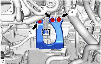
*a Bolt (A) *b Bolt (B) Engage the wire harness clamp and install the air cleaner bracket to the cylinder block sub-assembly and air conditioning wire with the bolt (A) and 2 bolts (B).
- Torque:
- Bolt (A)
- 12.5 N*m { 127 kgf*cm, 9 ft.*lbf }
- Bolt (B)
- 12 N*m { 122 kgf*cm, 9 ft.*lbf }
-
-
INSTALL AIR CLEANER CASE SUB-ASSEMBLY
-
Install the air cleaner case sub-assembly to the air cleaner bracket with the 2 bolts.
- Torque:
- 4.0 N*m { 41 kgf*cm, 35 in.*lbf }
-
-
INSTALL AIR CLEANER FILTER ELEMENT SUB-ASSEMBLY
-
Install the air cleaner filter element sub-assembly to the air cleaner case sub-assembly.
-
-
INSTALL NO. 2 AIR CLEANER INLET
-
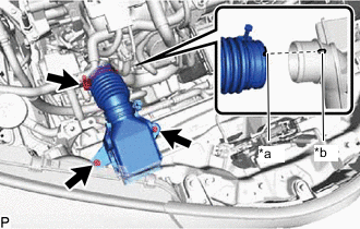
*a Groove *b Protrusion Temporarily install the No. 2 air cleaner inlet to the No. 1 air cleaner inlet and upper radiator support sub-assembly with the 2 bolts.
Tech Tips
Align the protrusion of the No. 1 air cleaner inlet with the groove of the No. 2 air cleaner inlet.
-
Tighten the 2 bolts.
- Torque:
- 4.0 N*m { 41 kgf*cm, 35 in.*lbf }
-
Tighten the hose clamp.
- Torque:
- 2.0 N*m { 20 kgf*cm, 18 in.*lbf }
-
-
INSTALL RADIATOR COVER
-
INSTALL THROTTLE BODY ASSEMBLY
-
INSPECT INTAKE SYSTEM
Tech Tips
Perform Inspection After Repair after repairing any vacuum leaks in the intake system.