FUEL TANK REMOVAL
CAUTION / NOTICE / HINT
The necessary procedures (adjustment, calibration, initialization or registration) that must be performed after parts are removed and installed, or replaced during fuel tank assembly removal/installation are shown below.
| Replaced Part or Performed Procedure | Necessary Procedure | Effect/Inoperative Function when Necessary Procedure not Performed | Link |
|---|---|---|---|
| Disconnect cable from negative auxiliary battery terminal | Memorize steering angle neutral point | Lane departure alert system (w/ Steering Control) | |
| Simple intelligent parking assist system*1 | |||
| Toyota parking assist-sensor system*1 | |||
| Pre-collision system | |||
| Initialize back door lock | Power door lock control system | ||
| Gas leak from exhaust system is repaired | Inspection After Repair |
|
*1: When performing learning using the GTS.
CAUTION:
-
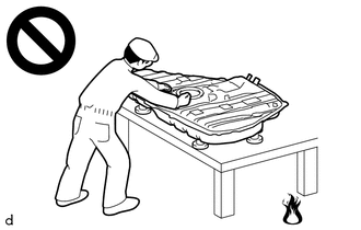
Never perform work on fuel system components near any possible ignition sources.
-
Vaporized fuel could ignite, resulting in a serious accident.
PROCEDURE
-
REMOVE FUEL SUCTION TUBE WITH PUMP AND GAUGE ASSEMBLY
-
DRAIN FUEL
-
REMOVE TAIL EXHAUST PIPE ASSEMBLY
-
REMOVE REAR FLOOR SIDE MEMBER COVER LH
-
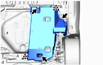
Remove the 3 bolts and clip (A).
-
Disengage the clip (B) to remove the rear floor side member cover LH.
-
-
REMOVE REAR FLOOR SIDE MEMBER COVER RH
-
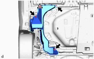
Remove the 3 bolts.
-
Disengage the clip to remove the rear floor side member cover RH.
-
-
REMOVE NO. 1 FUEL TANK PROTECTOR
-
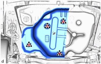
Remove the 4 clips and No. 1 fuel tank protector from the fuel tank assembly.
-
-
DISCONNECT FUEL TANK BREATHER TUBE
-

Disconnect the fuel tank breather tube from the fuel tank filler pipe sub-assembly.
-
-
DISCONNECT FUEL TANK TO FILLER PIPE HOSE
-
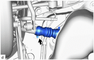
Loosen the clamp, then disconnect the fuel tank to filler pipe hose from the fuel tank assembly.
-
-
DISCONNECT FUEL TANK MAIN TUBE SUB-ASSEMBLY
-
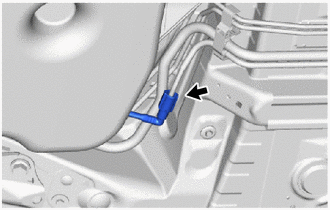
Disconnect the fuel tank main tube sub-assembly from the fuel pipe.
-
-
DISCONNECT FUEL TANK VENT HOSE SUB-ASSEMBLY
-
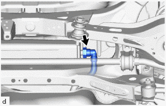
Disconnect the fuel tank vent hose sub-assembly from the canister (charcoal canister assembly).
-
-
REMOVE FUEL TANK ASSEMBLY
CAUTION:
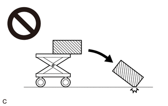
The fuel tank assembly is very heavy. Be sure to follow the procedure described in the repair manual, or the fuel tank assembly may fall off the engine lifter.
-
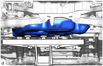
Support the fuel tank assembly using an engine lifter.
Tech Tips
Using height adjustment attachments and plate lift attachments, keep the fuel tank assembly horizontal.
-
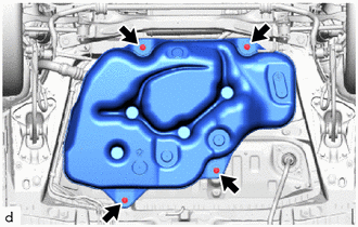
Remove the 4 bolts.
-
Lower the engine lifter to remove the fuel tank assembly.
Note
-
Be careful not to drop the fuel tank assembly.
-
When removing the fuel tank assembly, tilt it slightly to prevent it from interfering with the surrounding parts.
-
-
Remove the fuel tank side plate from the fuel tank assembly.
-
-
REMOVE FUEL TANK MAIN TUBE SUB-ASSEMBLY
-
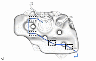
Disengage the 4 clamps to remove the fuel tank main tube sub-assembly from the fuel tank assembly.
-
-
REMOVE FUEL TANK VENT HOSE SUB-ASSEMBLY
-
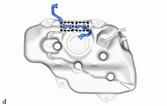
Disengage the 2 clamps to remove the fuel tank vent hose sub-assembly from the fuel tank assembly.
-