EGR VALVE REMOVAL

Info Added 2017-10-06 ![]()
CAUTION / NOTICE / HINT
The necessary procedures (adjustment, calibration, initialization or registration) that must be performed after parts are removed and installed, or replaced during EGR valve assembly removal/installation are shown below.
| Replaced Part or Performed Procedure | Necessary Procedures | Effect/Inoperative Function when Necessary Procedure not Performed | Link |
|---|---|---|---|
| Disconnect cable from negative auxiliary battery terminal | Memorize steering angle neutral point | Lane departure alert system (w/ Steering Control) | |
| Simple intelligent parking assist system*1 | |||
| Toyota parking assist-sensor system*1 | |||
| Pre-collision system | |||
| Initialize back door lock | Power door lock control system | ||
| Replacement of EGR valve assembly | Inspection After Repair |
|
*1: When performing learning using the GTS.
CAUTION:
-
Orange wire harnesses and connectors indicate high-voltage circuits. To prevent electric shock, always follow the procedure described in the repair manual.
-
To prevent electric shock, wear insulated gloves when working on wire harnesses and components of the high voltage system.
PROCEDURE
-
PRECAUTION
Note
After turning the power switch off, waiting time may be required before disconnecting the cable from the negative (-) auxiliary battery terminal. Therefore, make sure to read the disconnecting the cable from the negative (-) auxiliary battery terminal notices before proceeding with work.
-
DISCONNECT ENGINE WIRE
-
REMOVE AUXILIARY BATTERY
-
REMOVE SERVICE PLUG GRIP
-
REMOVE WINDSHIELD WIPER MOTOR AND LINK ASSEMBLY
-
REMOVE NO. 1 HEATER AIR DUCT SPLASH SHIELD SEAL
-
REMOVE WATER GUARD PLATE LH
-
REMOVE COWL BODY MOUNTING REINFORCEMENT LH
-
REMOVE COWL BODY MOUNTING REINFORCEMENT RH
-
REMOVE OUTER COWL TOP PANEL SUB-ASSEMBLY (for LHD)
-
REMOVE OUTER COWL TOP PANEL SUB-ASSEMBLY (for RHD)
-
REMOVE NO. 1 ENGINE UNDER COVER
-
DRAIN ENGINE COOLANT (for Engine)
-
REMOVE ECM
-
REMOVE BATTERY CLAMP SUB-ASSEMBLY
-
SEPARATE TRANSMISSION CONTROL CABLE ASSEMBLY
-
DISCONNECT ENGINE WIRE
-
REMOVE CONNECTOR COVER ASSEMBLY
-
CHECK TERMINAL VOLTAGE
-
TEMPORARILY INSTALL CONNECTOR COVER ASSEMBLY
-
DISCONNECT HV FLOOR UNDER WIRE
-
DISCONNECT HV AIR CONDITIONING WIRE
-
SEPARATE INVERTER WITH CONVERTER ASSEMBLY
CAUTION:
Wear insulated gloves.
-
Remove the 5 bolts and 2 nuts and separate the inverter with converter assembly.
Note
-
To prevent damage due to static electricity, do not touch the terminals of the inverter with converter assembly connector.
-
Make sure to seal the inverter with converter assembly with the connector cover assembly or tape (non-residue type) etc., to prevent entry of foreign matter and water.
-
-

*a Rope Using a rope or equivalent, secure the inverter with converter assembly with the hood hinge.
Note
-
Be careful not to damage the surrounding components when securing the inverter with converter assembly.
-
To prevent damage to the inverter with converter assembly, do not hold the coolant pipe, bracket or connector when securing the inverter with converter assembly.
-
To prevent damage due to static electricity, do not touch the terminals of the inverter with converter assembly connector.
-
Make sure to seal the inverter with converter assembly with the connector cover assembly or tape (non-residue type) etc., to prevent entry of foreign matter and water.
-
-
-
REMOVE EGR PIPE ASSEMBLY
-
REMOVE EGR VALVE ASSEMBLY
-

Disconnect the EGR valve assembly connector.
-

Slide the clip and disconnect the No. 6 water by-pass hose from the EGR valve assembly.
-

Slide the clip and disconnect the water by-pass hose from the EGR valve assembly.
-

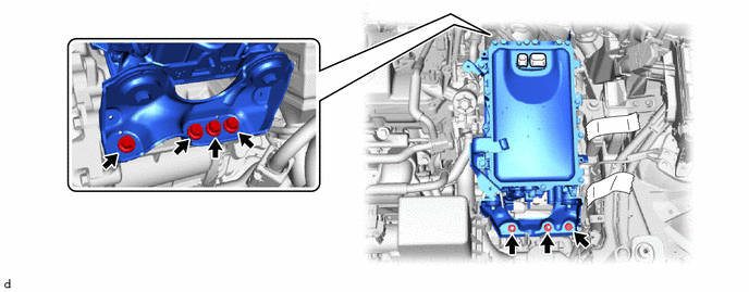
Remove the 3 nuts.
-

Using an E8 "TORX" socket wrench, remove the stud bolt from the camshaft housing sub-assembly.
Tech Tips
If a stud bolt is deformed or the threads are damaged, replace it.
-
Remove the EGR valve assembly from the EGR pipe with cooler sub-assembly.
-

Remove the EGR valve gasket from the EGR valve assembly.
-