EGR VALVE INSTALLATION

PROCEDURE
-
INSTALL EGR VALVE ASSEMBLY
-
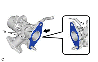
*a Claw Install a new EGR valve gasket to the EGR valve assembly.
Note
Make sure that the claws of the EGR valve gasket are toward the EGR valve assembly side.
-
Set the EGR valve assembly to the EGR pipe with cooler sub-assembly.
-
Using an E8 "TORX" socket wrench, install the stud bolt to the camshaft housing sub-assembly.
- Torque:
- 9.5 N*m { 97 kgf*cm, 84 in.*lbf }
Tech Tips
If a stud bolt is deformed or the threads are damaged, replace it.
-
Install the EGR valve assembly to the EGR pipe with cooler sub-assembly with the 3 nuts.
- Torque:
- 21 N*m { 214 kgf*cm, 15 ft.*lbf }
-
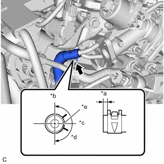
*a 0 to 4 mm (0 to 0.157 in.) *b Top of Vehicle *c Left Side of Vehicle *d 180° *e Paint Mark Connect the water by-pass hose to the EGR valve assembly and slide the clip to secure it.
-
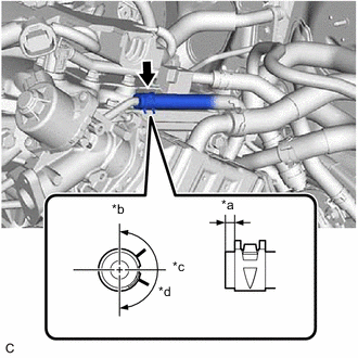
*a 0 to 4 mm (0 to 0.157 in.) *b Top of Vehicle *c Left Side of Vehicle *d 180° Connect the No. 6 water by-pass hose to the EGR valve assembly and slide the clip to secure it.
-
Connect the EGR valve assembly connector.
-
-
INSTALL EGR PIPE ASSEMBLY
-
INSTALL INVERTER WITH CONVERTER ASSEMBLY
CAUTION:
Wear insulated gloves.
Note
-
Be careful not to damage the surrounding components when installing the inverter with converter assembly.
-
To prevent damage to the inverter with converter assembly, do not hold the coolant pipe, bracket or connector when securing the inverter with converter assembly.
-
To prevent damage due to static electricity, do not touch the terminals of the inverter with converter assembly connector.
-
Make sure to seal the inverter with converter assembly with the connector cover assembly or tape (non-residue type) etc., until just before installing the inverter with converter assembly to prevent entry of foreign matter and water.
-
Remove the rope or equivalent that was securing the inverter with converter assembly.
-
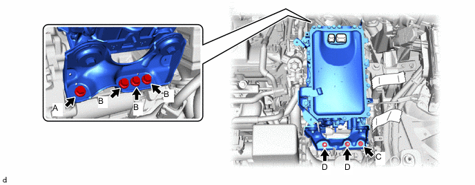
Temporarily install the inverter with converter assembly with the 5 bolts and 2 nuts.
Note
Make sure that the inverter with converter assembly is positioned so that the stud bolts are in contact with the base of the U-shaped portions of the No. 1 inverter bracket.
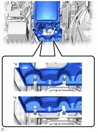
*a Correct *b Incorrect -
Fully tighten the bolt (A).
- Torque:
- 25 N*m { 255 kgf*cm, 18 ft.*lbf }
-
Fully tighten the 3 bolts (B).
- Torque:
- 25 N*m { 255 kgf*cm, 18 ft.*lbf }
-
Fully tighten the bolt (C).
- Torque:
- 25 N*m { 255 kgf*cm, 18 ft.*lbf }
-
Fully tighten the 2 nuts (D).
- Torque:
- 25 N*m { 255 kgf*cm, 18 ft.*lbf }
-
-
CONNECT HV AIR CONDITIONING WIRE
-
CONNECT HV FLOOR UNDER WIRE
-
CONNECT ENGINE WIRE
-
CONNECT TRANSMISSION CONTROL CABLE ASSEMBLY
-
INSTALL BATTERY CLAMP SUB-ASSEMBLY
-
INSTALL ECM
-
INSTALL SERVICE PLUG GRIP
-
INSTALL AUXILIARY BATTERY
-
CONNECT ENGINE WIRE
-
INSTALL OUTER COWL TOP PANEL SUB-ASSEMBLY (for LHD)
-
INSTALL OUTER COWL TOP PANEL SUB-ASSEMBLY (for RHD)
-
INSTALL COWL BODY MOUNTING REINFORCEMENT LH
-
INSTALL COWL BODY MOUNTING REINFORCEMENT RH
-
INSTALL WATER GUARD PLATE LH
-
INSTALL NO. 1 HEATER AIR DUCT SPLASH SHIELD SEAL
-
INSTALL WINDSHIELD WIPER MOTOR AND LINK ASSEMBLY
-
ADD ENGINE COOLANT (for Engine)
-
INSPECT FOR COOLANT LEAK (for Engine)
-
INSTALL NO. 1 ENGINE UNDER COVER