FUEL INJECTOR REMOVAL

Info Added 2017-10-06 ![]()
CAUTION / NOTICE / HINT
The necessary procedures (adjustment, calibration, initialization or registration) that must be performed after parts are removed and installed, or replaced during fuel injector assembly removal/installation are shown below.
| Replaced Part or Performed Procedure | Necessary Procedure | Effect/Inoperative Function when Necessary Procedure not Performed | Link |
|---|---|---|---|
| Disconnect cable from negative auxiliary battery terminal | Memorize steering angle neutral point | Lane departure alert system (w/ Steering Control) | |
| Simple intelligent parking assist system*1 | |||
| Toyota parking assist-sensor system*1 | |||
| Pre-collision system | |||
| Initialize back door lock | Power door lock control system | ||
|
Inspection after repair |
|
*1: When performing learning using the GTS.
PROCEDURE
-
PRECAUTION
Note
After turning the power switch off, waiting time may be required before disconnecting the cable from the negative (-) auxiliary battery terminal. Therefore, make sure to read the disconnecting the cable from the negative (-) auxiliary battery terminal notices before proceeding with work.
-
DISCHARGE FUEL SYSTEM PRESSURE
-
DISCONNECT CABLE FROM NEGATIVE AUXILIARY BATTERY TERMINAL
Note
When disconnecting the cable, some systems need to be initialized after the cable is reconnected.
-
REMOVE EGR PIPE WITH COOLER SUB-ASSEMBLY
-
DISCONNECT NO. 2 VENTILATION HOSE
-
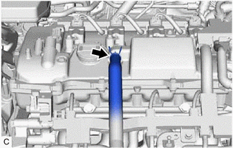
Slide the clip and disconnect the No. 2 ventilation hose from the cylinder head cover sub-assembly.
-
-
DISCONNECT ENGINE WIRE
-
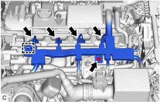
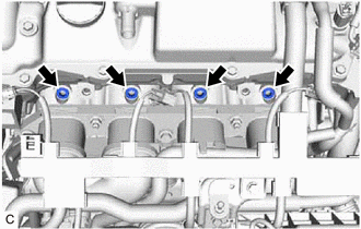
Disconnect the 4 fuel injector assembly connectors.
-
Remove the bolt.
-
Disengage the clamp to disconnect the engine wire.
-
-
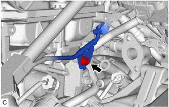
DISCONNECT FUEL TUBE SUB-ASSEMBLY
-
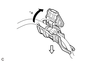
*a Open 
Pull Open the cover of the fuel pipe clamp and remove the fuel pipe clamp from the fuel tube connector.
-
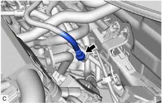
Disconnect the fuel tube sub-assembly from the fuel pipe.
-
-
REMOVE FUEL DELIVERY PIPE SUB-ASSEMBLY
-
Remove the bolt to separate the clamp of the fuel delivery pipe sub-assembly from the cylinder head sub-assembly.
-
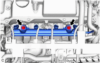
Remove the 2 bolts and fuel delivery pipe sub-assembly with the 4 fuel injector assemblies.
Note
Be careful not to drop the fuel injector assemblies when removing the fuel delivery pipe sub-assembly.
-
-
REMOVE NO. 1 DELIVERY PIPE SPACER
-
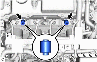
Remove the 2 No. 1 delivery pipe spacers from the cylinder head sub-assembly.
-
-
REMOVE FUEL INJECTOR ASSEMBLY
-
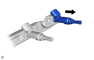
Pull the 4 fuel injector assemblies out of the fuel delivery pipe sub-assembly.
-
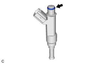
Remove the O-ring from each fuel injector assembly.
-
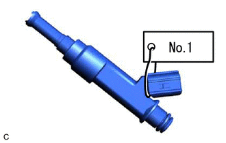
Attach a tag or label with the corresponding cylinder number to each fuel injector assembly so that they can be installed to their original locations.
Note
Cover the fuel injector assemblies with plastic bags to prevent damage and contamination.
-
Remove the 4 injector vibration insulators from the cylinder head sub-assembly.
-