ENGINE UNIT INSTALLATION

Info Added 2017-10-06 ![]()
PROCEDURE
-
INSTALL WIRE HARNESS CLAMP BRACKET
-
Install the wire harness clamp bracket to the timing chain cover assembly with the bolt.
- Torque:
- 8.0 N*m { 82 kgf*cm, 71 in.*lbf }
-
-
INSTALL IGNITION COIL ASSEMBLY
-
INSTALL VENTILATION HOSE
-
Install the ventilation hose to the PCV valve (ventilation valve sub-assembly) and slide the clip to secure it.
-
-
INSTALL FUEL INJECTOR ASSEMBLY
-
INSTALL NO. 1 DELIVERY PIPE SPACER
-
INSTALL FUEL DELIVERY PIPE SUB-ASSEMBLY
-
INSTALL FUEL VAPOR FEED PIPE
-
Install the fuel vapor feed pipe to cylinder head cover sub-assembly with the 2 bolts.
- Torque:
- 10 N*m { 102 kgf*cm, 7 ft.*lbf }
-
-
INSTALL PURGE VALVE (PURGE VSV)
-
INSTALL NO. 6 WATER BY-PASS PIPE
-
Install the No. 6 water by-pass pipe to the cylinder head sub-assembly with the 2 bolts.
- Torque:
- 21 N*m { 214 kgf*cm, 15 ft.*lbf }
-
Connect the No. 6 water by-pass pipe to the water inlet sub-assembly and slide the clip to secure it.
-
-
INSTALL WATER BY-PASS PIPE NO.5
-
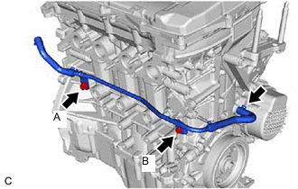
Install the No. 5 water by-pass pipe to the cylinder block sub-assembly with the 2 bolts.
- Torque:
- Bolt (A)
- 21 N*m { 214 kgf*cm, 15 ft.*lbf }
- Bolt (B)
- 10 N*m { 102 kgf*cm, 7 ft.*lbf }
-
Connect the No. 5 water by-pass pipe to the timing chain cover sub-assembly and slide the clip to secure it.
-
-
INSTALL ENGINE OIL LEVEL DIPSTICK GUIDE
-
INSTALL ENGINE OIL LEVEL DIPSTICK
-
INSTALL INTAKE MANIFOLD
-
CONNECT VENTILATION HOSE
-
INSTALL EXHAUST MANIFOLD (TWC: Front Catalyst)
-
INSTALL NO. 1 EXHAUST MANIFOLD HEAT INSULATOR
-
TEMPORARILY INSTALL EGR VALVE ASSEMBLY WITH EGR COOLER
-
Install a new EGR cooler gasket.
-
Using an E8 "TORX" socket wrench, temporarily install the EGR valve assembly with EGR cooler with the 2 stud bolts.
- Torque:
- 9.5 N*m { 97 kgf*cm, 84 in.*lbf }
-
Temporarily install the bolt and 4 nuts.
-
-
TEMPORARILY INSTALL EGR PIPE ASSEMBLY
-
Install new EGR pipe gasket and inlet EGR gasket.
-
Temporarily install the EGR pipe assembly with the 4 bolts.
-
-
INSTALL EGR VALVE ASSEMBLY WITH EGR COOLER
-
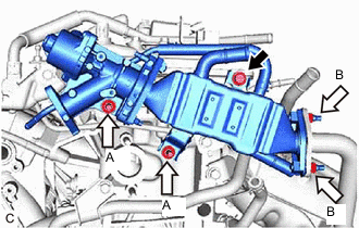

Bolt 
Nut Tighten the bolt and 4 nuts.
- Torque:
- Nut (A)
- 21 N*m { 214 kgf*cm, 15 ft.*lbf }
- Nut (B)
- 26 N*m { 265 kgf*cm, 19 ft.*lbf }
- Bolt
- 21 N*m { 214 kgf*cm, 15 ft.*lbf }
-
-
INSTALL EGR PIPE ASSEMBLY
-
Tighten the bolt and 4 bolts.
- Torque:
- 8.5 N*m { 87 kgf*cm, 75 in.*lbf }
-
-
INSTALL WATER OUTLET
-
Install the water outlet and a new water outlet gasket to the cylinder head sub-assembly with the 2 nuts.
- Torque:
- 28 N*m { 286 kgf*cm, 21 ft.*lbf }
-
Connect the No. 9 water by-pass hose to the purge valve and slide the clip to secure it.
-
Connect the No. 4 water by-pass hose to the EGR valve assembly with EGR cooler and slide the clip to secure it.
-
Connect the No. 7 water by-pass hose to the No. 2 water by-pass hose and slide the clip to secure it.
-