ENGINE UNIT INSPECTION

PROCEDURE
-
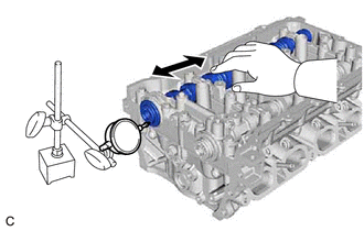
INSPECT NO. 1 VALVE ROCKER ARM SUB-ASSEMBLY
-
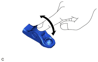
Turn the roller by hand to check that it turns smoothly.
Tech Tips
If the roller does not turn smoothly, replace the No. 1 valve rocker arm sub-assembly.
-
-
INSPECT VALVE LASH ADJUSTER ASSEMBLY
Note
-
Keep the valve lash adjuster assembly free from dirt and foreign matter.
-
Only use clean engine oil.
-
Place the valve lash adjuster assembly into a container filled with engine oil.
-
Insert the tip of SST into the valve lash adjuster assembly plunger and use the tip to press down on the check ball inside the plunger.
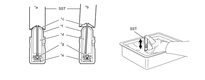
*a Correct *b Incorrect *c Taper *d Low Pressure Chamber *e High Pressure Chamber *f Plunger *g Check Ball - - - SST
- 09276-75010
-
Squeeze SST and the valve lash adjuster assembly together to move the plunger up and down 5 to 6 times.
-
Check the movement of the plunger and bleed the air.
OK Plunger moves up and down. Note
When bleeding air from the high-pressure chamber, make sure that the tip of SST is actually pressing the check ball as shown in the illustration. If the check ball is not pressed, air will not bleed.
-
After bleeding the air, remove SST. Then try to quickly and firmly press the plunger by hand.
OK Plunger is very difficult to move. Tech Tips
If the plunger is easy to move, replace the valve lash adjuster assembly.
-
-
INSPECT CHAIN SUB-ASSEMBLY
-
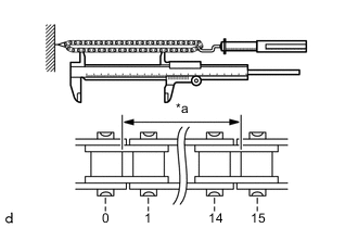
*a Measurement Length Using a spring scale, pull the chain sub-assembly with a force of 147 N (15 kgf, 33.0 lbf) as shown in the illustration.
-
Using a vernier caliper, measure the length of 15 links.
Maximum Chain Elongation 115.2 mm (4.54 in.) Note
Perform the measurement at 3 random places. Use the average of the measurements.
Tech Tips
If the average elongation is more than the maximum, replace the chain sub-assembly.
-
-
INSPECT NO. 2 CHAIN SUB-ASSEMBLY
-

*a Measurement Length Using a spring scale, pull the No. 2 chain sub-assembly with a force of 147 N (15 kgf, 33.0 lbf) as shown in the illustration.
-
Using a vernier caliper, measure the length of 15 links.
Maximum Chain Elongation 102.1 mm (4.02 in.) Note
Perform the measurement at 3 random places. Use the average of the measurements.
Tech Tips
If the average elongation is more than the maximum, replace the No. 2 chain sub-assembly.
-
-
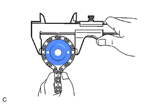
INSPECT OIL PUMP DRIVE GEAR
-
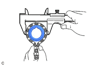
Place the No. 2 chain sub-assembly around the oil pump drive gear.
-
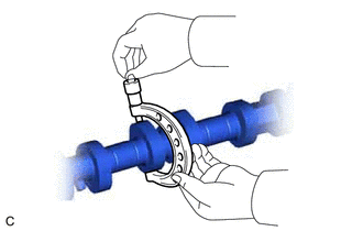
Using a vernier caliper, measure the diameter of the oil pump drive gear and No. 2 chain sub-assembly.
Minimum Gear Diameter (with No. 2 Chain Sub-assembly) 48.2 mm (1.90 in.) Note
The vernier caliper must be in contact with the chain rollers when measuring.
Tech Tips
If the diameter is less than the minimum, replace the No. 2 chain sub-assembly and oil pump drive gear.
-
-
INSPECT OIL PUMP DRIVE SHAFT GEAR
-
Place the No. 2 chain sub-assembly around the oil pump drive shaft gear.
-
Using a vernier caliper, measure the diameter of the oil pump drive shaft gear and No. 2 chain sub-assembly.
Minimum Gear Diameter (with No. 2 Chain Sub-assembly) 48.2 mm (1.90 in.) Note
The vernier caliper must be in contact with the chain rollers when measuring.
Tech Tips
If the diameter is less than the minimum, replace the No. 2 chain sub-assembly and oil pump drive shaft gear.
-
-
INSPECT CAMSHAFT TIMING GEAR ASSEMBLY
-
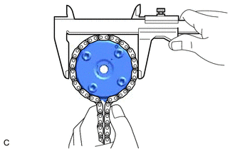
Place the chain sub-assembly around the camshaft timing gear assembly.
-
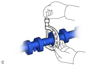
Using a vernier caliper, measure the diameter of the camshaft timing gear assembly and chain sub-assembly.
Minimum Gear Diameter (with Chain Sub-assembly) 96.8 mm (3.81 in.) Note
The vernier caliper must be in contact with the chain rollers when measuring.
Tech Tips
If the diameter is less than the minimum, replace the chain sub-assembly and camshaft timing gear assembly.
-
-
INSPECT CAMSHAFT TIMING SPROCKET
-
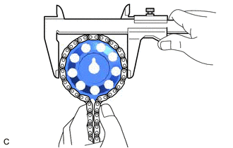
Place the chain sub-assembly around the camshaft timing sprocket.
-
Using a vernier caliper, measure the diameter of the camshaft timing sprocket and chain sub-assembly.
Minimum Gear Diameter (with Chain Sub-assembly) 96.8 mm (3.81 in.) Note
The vernier caliper must be in contact with the chain rollers when measuring.
Tech Tips
If the diameter is less than the minimum, replace the chain sub-assembly and camshaft timing sprocket.
-
-
INSPECT CRANKSHAFT TIMING SPROCKET
-
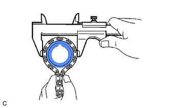
Place the chain sub-assembly around the crankshaft timing sprocket.
-
Using a vernier caliper, measure the diameter of the crankshaft timing sprocket and chain sub-assembly.
Minimum Sprocket Diameter (with Chain Sub-assembly) 51.1 mm (2.01 in.) Note
The vernier caliper must be in contact with the chain rollers when measuring.
Tech Tips
If the diameter is less than the minimum, replace the chain sub-assembly and crankshaft timing sprocket.
-
-
INSPECT CHAIN TENSIONER SLIPPER
-
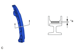
*a Depth Using a vernier caliper, measure the wear depth of the chain tensioner slipper.
Maximum Depth 1.0 mm (0.0394 in.) Tech Tips
If the depth is more than the maximum, replace the chain tensioner slipper.
-
-
INSPECT NO. 1 CHAIN VIBRATION DAMPER
-
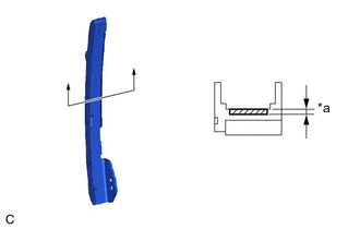
*a Depth Using a vernier caliper, measure the wear depth of the No. 1 chain vibration damper.
Maximum Depth 1.0 mm (0.0394 in.) Tech Tips
If the depth is more than the maximum, replace the No. 1 chain vibration damper.
-
-
INSPECT NO. 2 CHAIN VIBRATION DAMPER
-
*a Depth Using a vernier caliper, measure the wear depth of the No. 2 chain vibration damper.
Maximum Depth 1.0 mm (0.0394 in.) Tech Tips
If the depth is more than the maximum, replace the No. 2 chain vibration damper.
-
-
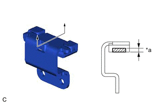
INSPECT CHAIN TENSIONER PLATE
-
*a Depth Using a vernier caliper, measure the wear depth of the chain tensioner plate.
Maximum Depth 1.0 mm (0.0394 in.) Tech Tips
If the depth is more than the maximum, replace the chain tensioner plate.
-
-
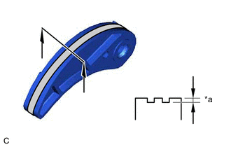
INSPECT NO. 1 CHAIN TENSIONER ASSEMBLY
-
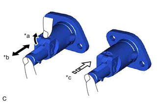
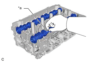
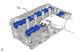
*a Raise *b Move *c Lock Check that the plunger moves smoothly when the cam is raised with your finger.
-
Release the cam, then check that the plunger is locked in place by the cam and does not move when pushed with your finger.
Tech Tips
If the plunger does not move smoothly, replace the No. 1 chain tensioner assembly.
-
-
INSPECT CAMSHAFT
-
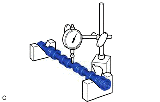
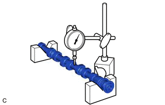
Inspect the camshaft for runout.
-
Place the camshaft on V-blocks.
-
Using a dial indicator, measure the runout at the center journal.
Maximum Runout 0.03 mm (0.00118 in.) Tech Tips
If the runout is more than the maximum, replace the camshaft.
-
-
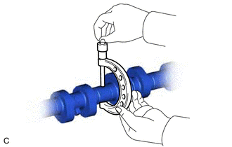
Inspect the cam lobes.
-
Using a micrometer, measure the cam lobe height.
Standard Cam Lobe Height 42.816 to 42.916 mm (1.6857 to 1.6896 in.) Minimum Cam Lobe Height 42.766 mm (1.6837 in.) Tech Tips
If the cam lobe height is less than the minimum, replace the camshaft.
-
-
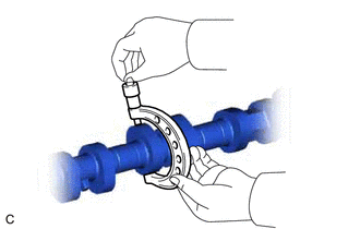
Inspect the camshaft journals.
-
Using a micrometer, measure the journal diameter.
Standard Journal Diameter Journal Position Specified Condition No. 1 34.449 to 34.465 mm (1.3563 to 1.3569 in.) Others 22.949 to 22.965 mm (0.90350 to 0.90413 in.)
-
-
-
INSPECT NO. 2 CAMSHAFT
-
Inspect the No. 2 camshaft for runout.
-
Place the No. 2 camshaft on V-blocks.
-
Using a dial indicator, measure the runout at the center journal.
Maximum Runout 0.03 mm (0.00118 in.) Tech Tips
If the runout is more than the maximum, replace the No. 2 camshaft.
-
-
Inspect the cam lobes.
-
Using a micrometer, measure the cam lobe height.
Standard Cam Lobe Height 43.344 to 43.444 mm (1.7065 to 1.7104 in.) Minimum Cam Lobe Height 43.294 mm (1.7045 in.) Tech Tips
If the cam lobe height is less than the minimum, replace the No. 2 camshaft.
-
-
Inspect the No. 2 camshaft journals.
-
Using a micrometer, measure the journal diameter.
Standard Journal Diameter Journal Position Specified Condition No. 1 34.449 to 34.465 mm (1.3563 to 1.3569 in.) Others 22.949 to 22.965 mm (0.90350 to 0.90413 in.) Tech Tips
If the journal diameter is not as specified, check the No. 2 camshaft oil clearance.
-
-
-
INSPECT CYLINDER HEAD SET BOLT
-
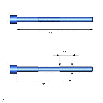
*a Measurement Length *b Measurement Area *c 115 mm (4.53 in.) Using a vernier caliper, measure the length of the cylinder head set bolt from the seat to the end.
Standard Length 146.8 to 148.2 mm (5.78 to 5.83 in.) Maximum Length 149.2 mm (5.87 in.) Note
-
If the length is greater than the maximum, replace the cylinder head set bolt with a new one. Failure to do so may lead to engine damage.
-
If there is any thread deformation, replace the cylinder head set bolt with a new one.
-
-
Using a vernier caliper, measure the diameter of the threads at several points within the area shown in the illustration.
Standard Diameter 9.77 to 9.96 mm (0.385 to 0.392 in.) Minimum Diameter 9.4 mm (0.370 in.) Note
-
Diameter measurements should be done at several points.
-
If the diameter is less than the minimum, replace the cylinder head set bolt with a new one. Failure to do so may lead to engine damage.
-
If there is any thread deformation, replace the cylinder head set bolt with a new one.
-
-
-
INSPECT CAMSHAFT THRUST CLEARANCE
-
Clean the camshaft, No. 2 camshaft and camshaft bearing caps.
-
Place the camshaft, No. 2 camshaft and camshaft housing sub-assembly on the cylinder head.
-
Install the camshaft bearing caps.
-
Install the camshaft housing sub-assembly.
-
Using a dial indicator, measure the thrust clearance while moving the camshaft and No. 2 camshaft back and forth.
Standard Thrust Clearance 0.06 to 0.155 mm (0.00236 to 0.00610 in.) Maximum Thrust Clearance 0.17 mm (0.00669 in.) Tech Tips
If the thrust clearance is more than the maximum, replace the camshaft housing sub-assembly. If the thrust surface is damaged, replace the camshaft.
-
-
INSPECT CAMSHAFT OIL CLEARANCE
-
Clean the camshaft bearing caps and camshaft journals.
-
Place the camshaft, No. 2 camshaft and camshaft housing sub-assembly on the cylinder head.
-
*a Plastigage Lay a strip of Plastigage across each of the camshaft journals.
-
Install the camshaft bearing caps.
Note
Do not turn the camshaft.
-
Remove the camshaft bearing caps.
-
*a Plastigage Measure the Plastigage at its widest point.
Standard Oil Clearance Item Specified Condition No. 1 Journal 0.030 to 0.063 mm (0.00118 to 0.00248 in.) Other Journals 0.035 to 0.072 mm (0.00138 to 0.00283 in.) Maximum Oil Clearance Item Specified Condition No. 1 Journal 0.085 mm (0.00335 in.) Other Journals 0.09 mm (0.00354 in.) Note
Completely remove the Plastigage after the inspection.
Tech Tips
If the oil clearance is greater than the maximum, replace the camshaft or No. 2 camshaft. If necessary, replace the cylinder head sub-assembly.
-
-
INSPECT EXHAUST MANIFOLD (TWC: Front Catalyst)
-
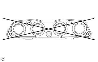
Using a precision straightedge and feeler gauge, check the surface that contacts the cylinder head sub-assembly for warpage.
Maximum Warpage 0.7 mm (0.0276 in.) Tech Tips
If the warpage is more than the maximum, replace the exhaust manifold (TWC: Front Catalyst).
-