ENGINE UNIT REMOVAL

Info Added 2017-10-06 ![]()
CAUTION / NOTICE / HINT
The necessary procedures (adjustment, calibration, initialization, or registration) that must be performed after parts are removed and installed, or replaced during engine unit removal/installation are shown below.
| Replaced Part or Performed Procedure | Necessary Procedure | Effect/Inoperative Function when Necessary Procedure not Performed | Link |
|---|---|---|---|
| Replacement of inverter with converter assembly | Resolver learning |
|
|
for SFI system |
Perform Vehicle Identification Number (VIN) registration | MIL comes on | |
for SFI system |
Inspection After Repair |
|
|
| Suspension, tires, etc. (The vehicle height changes because of suspension or tire replacement) |
Initialize No. 1 headlight ECU sub-assembly LH | Automatic headlight beam level control system | |
| Front wheel alignment adjustment |
|
|
for Initialization: for Calibration: |
| Replacement of hybrid vehicle transaxle assembly |
|
|
PROCEDURE
-
REMOVE WATER OUTLET
-
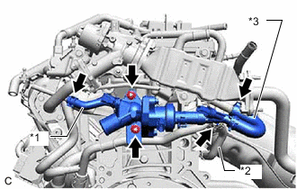
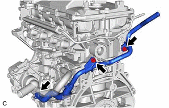
*1 No. 9 Water By-pass Hose *2 No. 7 Water by-pass Hose *3 No. 4 Water By-pass Hose Slide the clip and disconnect the No. 7 water by-pass hose from the No. 2 water by-pass hose.
-
Slide the clip and disconnect the No. 4 water by-pass hose from the EGR valve assembly with EGR cooler.
-
Slide the clip and disconnect the No. 9 water by-pass hose from the purge valve.
-
Remove the 2 nuts, water outlet and water outlet gasket from the cylinder head sub-assembly.
-
-
REMOVE EGR PIPE ASSEMBLY
-
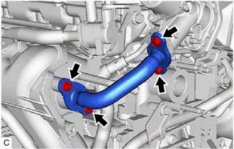
Remove the 4 bolts and EGR pipe assembly, EGR pipe gasket and inlet EGR gasket.
-
-
REMOVE EGR VALVE ASSEMBLY WITH EGR COOLER
-
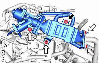

Bolt 
Nut *a Stud bolt Remove the bolt and 4 nuts.
-
Using an E8 "TORX" socket wrench, remove the 2 stud bolts and EGR valve assembly with EGR cooler from the cylinder head sub-assembly and exhaust manifold (TWC: Front Catalyst).
-
Remove the EGR cooler gasket.
-
-
REMOVE NO. 1 EXHAUST MANIFOLD HEAT INSULATOR
-
REMOVE MANIFOLD STAY
-
REMOVE EXHAUST MANIFOLD (TWC: Front Catalyst)
-
DISCONNECT VENTILATION HOSE
-
REMOVE INTAKE MANIFOLD
-
REMOVE ENGINE OIL LEVEL DIPSTICK
-
REMOVE ENGINE OIL LEVEL DIPSTICK GUIDE
-
REMOVE WATER BY-PASS PIPE NO.5
-
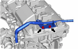
Slide the clip and disconnect the No. 5 water by-pass pipe from the timing chain cover sub-assembly.
-
Remove the 2 bolts and No. 5 water by-pass pipe from the cylinder block sub-assembly.
-
-
REMOVE NO. 6 WATER BY-PASS PIPE
-
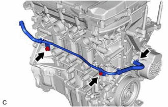
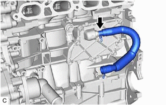
Slide the clip and disconnect the No. 6 water by-pass pipe from the water inlet sub-assembly.
-
Remove the 2 bolts and No. 6 water by-pass pipe from the cylinder head sub-assembly.
-
-
REMOVE PURGE VALVE (PURGE VSV)
-
REMOVE FUEL VAPOR FEED PIPE
-
Remove the 2 bolts and fuel vapor feed pipe from the cylinder head cover sub-assembly.
-
-
REMOVE FUEL DELIVERY PIPE SUB-ASSEMBLY
-
REMOVE NO. 1 DELIVERY PIPE SPACER
-
REMOVE FUEL INJECTOR ASSEMBLY
-
REMOVE VENTILATION HOSE
-
Slide the clip and remove the ventilation hose from the PCV valve (ventilation valve sub-assembly).
-
-
REMOVE IGNITION COIL ASSEMBLY
-
REMOVE WIRE HARNESS CLAMP BRACKET
-
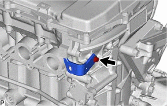
Remove the bolt and wire harness clamp bracket from the timing chain cover sub-assembly.
-