FRAME WIRE INSTALLATION
PROCEDURE
-
INSTALL HV FLOOR UNDER WIRE
CAUTION:
Wear insulated gloves.
-
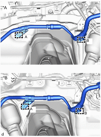
*A for LHD *B for RHD Engage the clamp (B).
-
Install a new clamp (A).
-
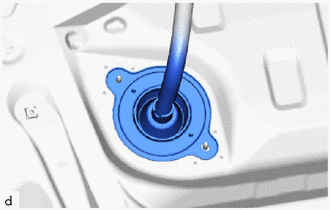
Insert the HV floor under wire into the floor panel hole and engage the grommet.
-
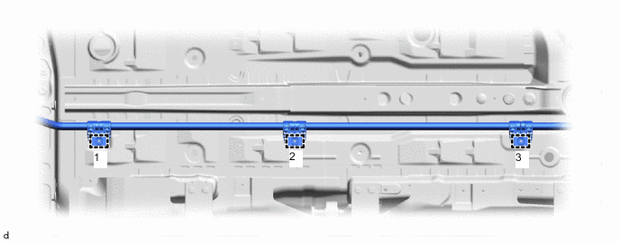
Install 3 new clamps in the order shown in the illustration.
-
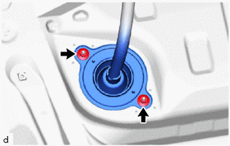
Install the HV floor under wire with the 2 nuts.
- Torque:
- 8.5 N*m { 87 kgf*cm, 75 in.*lbf }
-
-
INSTALL FRONT SUSPENSION CROSSMEMBER SUB-ASSEMBLY
-
INSTALL FRONT FLOOR COVER RH
-
INSTALL REAR FLOOR SIDE MEMBER COVER RH
-
CONNECT HV FLOOR UNDER WIRE
CAUTION:
Wear insulated gloves.
-
Connect the shield ground to the HV battery.
-
Connect the 2 HV battery junction block assembly connectors.
Note
Make sure that the connectors are connected securely.
-
-
INSTALL NO. 1 HV BATTERY COVER PANEL RH
-
INSTALL REAR SEAT CUSHION LEG SUB-ASSEMBLY
-
INSTALL REAR UNDER COVER
-
INSTALL REAR UNDER SIDE COVER LH
-
INSTALL REAR DOOR SCUFF PLATE LH
-
INSTALL REAR UNDER SIDE COVER RH
-
INSTALL REAR DOOR SCUFF PLATE RH
-
INSTALL REAR SEAT CUSHION LOCK HOOK
-
INSTALL BENCH TYPE REAR SEAT CUSHION ASSEMBLY
-
CONNECT HV FLOOR UNDER WIRE
-
CONNECT ENGINE WIRE
CAUTION:
Wear insulated gloves.
Note
Do not allow any foreign matter or water to enter the inverter with converter assembly.
-
Engage the 2 clamps and connect the engine wire.
-
Install the bolt.
- Torque:
- 8.0 N*m { 82 kgf*cm, 71 in.*lbf }
-
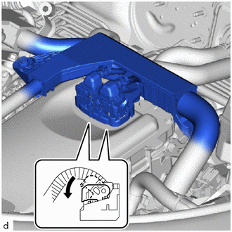
Connect the 2 inverter with converter assembly connectors and move each lock lever as shown in the illustration.
Note
-
To prevent damage due to static electricity, do not touch the terminals of the disconnected connectors.
-
Do not damage the terminals, connector housing or inverter with converter assembly when connecting the connectors.
-
Do not touch the waterproof seal or terminals of the connector.
-
-
-
INSTALL SERVICE PLUG GRIP