HV BATTERY THERMISTOR REMOVAL
Info Added 2017-10-06 ![]()
CAUTION / NOTICE / HINT
The necessary procedures (adjustment, calibration, initialization, or registration) that must be performed after parts are removed and installed, or replaced during hybrid battery thermistor removal/installation are shown below.
| Replaced Part or Performed Procedure | Necessary Procedures | Effect/Inoperative Function when Necessary Procedure not Performed | Link |
|---|---|---|---|
| Disconnect cable from negative auxiliary battery terminal | Memorize steering angle neutral point | Lane departure alert system (w/ Steering Control) | |
| Simple intelligent parking assist system*1 | |||
| Toyota parking assist-sensor system*1 | |||
| Pre-collision system | |||
| Initialize back door lock | Power door lock control system |
Click here Click here
CAUTION:
-
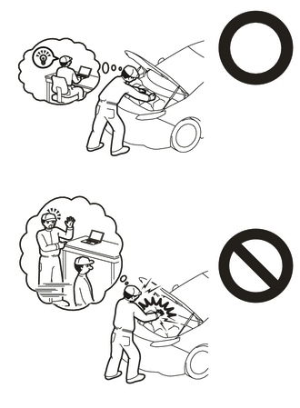
This vehicle has contains high voltage circuits standardized with orange colored wiring and connectors, so follow the instructions in this manual to perform the procedures correctly.
-
If the correct procedures are not followed according to the instructions in this manual, there is a danger of electric shock from the high voltage circuits.
-
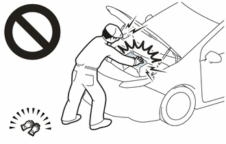
Be sure to wear insulating gloves when working on high voltage wiring or components.
-
If work is performed without wearing insulating gloves, there is a danger of electric shock.
PROCEDURE
-
PRECAUTION
Note
After turning the power switch off, waiting time may be required before disconnecting the cable from the negative (-) auxiliary battery terminal. Therefore, make sure to read the disconnecting the cable from the negative (-) auxiliary battery terminal notices before proceeding with work.
-
REMOVE HV BATTERY JUNCTION BLOCK ASSEMBLY
-
REMOVE NO. 1 HYBRID BATTERY SHIELD SUB-ASSEMBLY
CAUTION:
Be sure to wear insulated gloves and protective goggles.
-
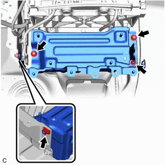
Remove the 4 nuts.
-
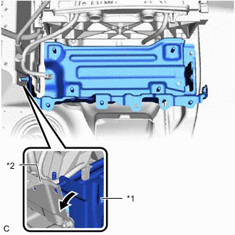
*1 No. 1 Hybrid Battery Shield Sub-assembly *2 No. 2 Hybrid Battery Shield Sub-assembly 
Pull Back Pull back the No. 2 hybrid battery shield sub-assembly and remove the No. 1 hybrid battery shield sub-assembly from the HV battery.
Tech Tips
Pull back the No. 2 hybrid battery shield sub-assembly until it is separated from the stud bolt of the No. 1 hybrid battery shield sub-assembly.
-
-
REMOVE NO. 1 HYBRID BATTERY INTAKE DUCT
CAUTION:
Be sure to wear insulated gloves and protective goggles.
-
Disengage the claw of hybrid battery thermistor (sensor portion) and disconnect the hybrid battery thermistor from the No. 1 hybrid battery intake duct.
-
Disengage the claw to remove the No. 1 hybrid battery intake duct from the HV battery.
-
-
REMOVE HYBRID BATTERY THERMISTOR
CAUTION:
Be sure to wear insulated gloves and protective goggles.
-
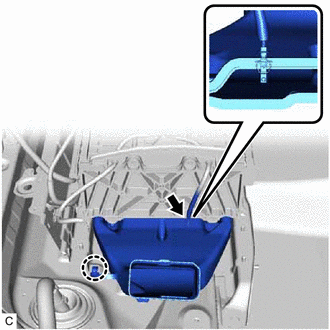
Disengage the clamp.
-
Disengage the 2 claws and remove the No. 1 hybrid battery packing from the HV battery.
-
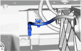
Disengage the clamp.
-
Disconnect the battery voltage sensor connector.
-
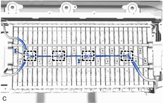
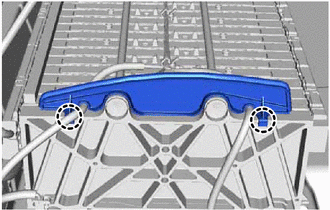
Disengage the 4 clamps.
-
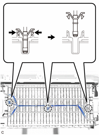
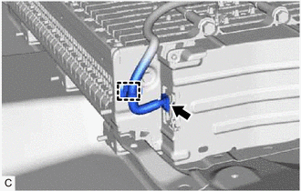
Disengage the 3 claws of the hybrid battery thermistor (sensor portions) and remove the hybrid battery thermistor from the HV battery.
-