MOTOR GENERATOR CONTROL SYSTEM, Diagnostic DTC:P1CAC49, P1C641F, P1CAF38
Info Added 2017-10-06 ![]()
| DTC Code | DTC Name |
|---|---|
| P1CAC49 | Generator Position Sensor Internal Electronic Failure |
| P1C641F | Generator Control Module Circuit Intermittent |
| P1CAF38 | Generator Position Sensor REF Signal Cycle Malfunction Signal Frequency Incorrect |
DESCRIPTION
The motor generator control ECU (MG ECU), which is built into the inverter with converter assembly, monitors its internal operation and detects malfunctions.
| DTC No. | Detection Item | DTC Detection Condition | Trouble Area | MIL | Warning Indicate |
|---|---|---|---|---|---|
| P1C641F | Generator Control Module Circuit Intermittent | Excitation signal (REF signal) for resolver angle detection cycle malfunction detected when DTC P0C7917, P0D3319, P1C5D19 or P1C5F19 is stored. (1 trip detection logic) |
|
Does not come on | Master Warning Light: Does not come on |
| P1CAC49 | Generator Position Sensor Internal Electronic Failure | Generator resolver angle malfunction: The difference between the resolver angle for control and estimated resolver angle exceeds the allowable limit. (1 trip detection logic) |
|
Comes on | Master Warning Light: Comes on |
| P1CAF38 | Generator Position Sensor REF Signal Cycle Malfunction Signal Frequency Incorrect | Resolver REF signal cycle malfunction: Excitation signal (REF signal) for resolver angle detection cycle malfunction (1 trip detection logic) |
|
Comes on | Master Warning Light: Comes on |
| DTC No. | Data List |
|---|---|
| P1CAC49 | Generator Revolution |
| P1CAF28 |
CONFIRMATION DRIVING PATTERN
Tech Tips
After repair has been completed, clear the DTC and then check that the vehicle has returned to normal by performing the following All Readiness check procedure.
-
Connect the GTS to the DLC3.
-
Turn the power switch on (IG) and turn the GTS on.
-
Clear the DTCs (even if no DTCs are stored, perform the clear DTC procedure).
-
Turn the power switch off and wait for 2 minutes or more.
-
Turn the power switch on (IG) and turn the GTS on.
-
With power switch on (IG) and wait for 5 seconds or more.*
*: Lightly wiggle the connectors and wire harnesses up and down and right and left.
-
Turn the power switch on (READY) with the shift lever in P and wait for 5 seconds or more.
-
Depress the accelerator pedal of the vehicle with the engine stopped and the shift lever in P to start the engine.
-
Keep the engine running for 5 seconds or more.
-
Drive the vehicle forward with the shift lever in D and drive the vehicle forward for 5 m (16 ft.) or more.
-
Drive the vehicle backward with the shift lever in R and drive the vehicle backward for 5 m (16 ft.) or more.
-
Enter the following menus: Powertrain / Motor Generator / Utility / All Readiness.
-
Check the DTC judgment result.
Tech Tips
-
If the judgment result shows NORMAL, the system is normal.
-
If the judgment result shows ABNORMAL, the system has a malfunction.
-
If the judgment result shows INCOMPLETE or N/A, perform driving pattern again.
-
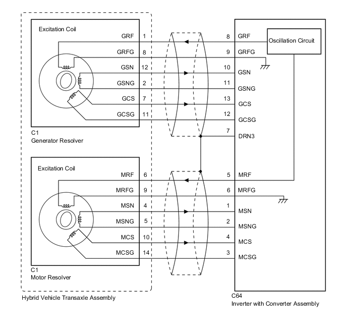
WIRING DIAGRAM
CAUTION / NOTICE / HINT
CAUTION:
-
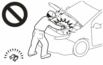
Before the following operations are conducted, take precautions to prevent electric shock by turning the power switch off, wearing insulated gloves, and removing the service plug grip from HV battery.
-
Inspecting the high-voltage system
-
Disconnecting the low voltage connector of the inverter with converter assembly
-
Disconnecting the low voltage connector of the HV battery
-
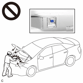
To prevent electric shock, make sure to remove the service plug grip to cut off the high voltage circuit before servicing the vehicle.
-
After removing the service plug grip from the HV battery, put it in your pocket to prevent other technicians from accidentally reconnecting it while you are working on the high-voltage system.
-
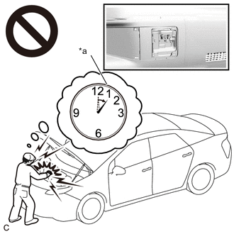
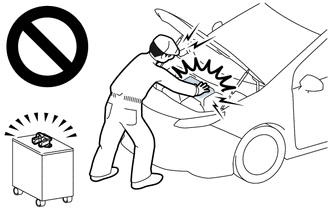
*a Without waiting for 10 minutes After removing the service plug grip, wait for at least 10 minutes before touching any of the high-voltage connectors or terminals. After waiting for 10 minutes, check the voltage at the terminals in the inspection point in the inverter with converter assembly. The voltage should be 0 V before beginning work.
Tech Tips
Waiting for at least 10 minutes is required to discharge the high-voltage capacitor inside the inverter with converter assembly.
Note
After turning the power switch off, waiting time may be required before disconnecting the cable from the negative (-) auxiliary battery terminal. Therefore, make sure to read the disconnecting the cable from the negative (-) auxiliary battery terminal notices before proceeding with work.
Tech Tips
-
If the problem symptom cannot be reproduced, performing a road test on a road on which the vehicle tends to vibrate will make it easier to reproduce the symptom.
-
If the resolver is malfunctioning, the vehicle may not drive smoothly.
-
When inspecting the connectors, if it is difficult to judge if a connector was disconnected, deformed or improperly secured, disconnect and reconnect the connector and then check for DTCs again. Check if the same DTC is output. If the same DTC is not output, improper connection of connectors is suspected.
-
As a malfunction detection threshold may be exceeded when performing the vibration or heat connector inspections, make sure to perform the following inspection to check that the DTC was not stored due to the malfunction of a part.
PROCEDURE
-
CHECK DTC OUTPUT (MOTOR GENERATOR CONTROL)
-
Connect the GTS to the DLC3.
-
Turn the power switch on (IG).
-
Enter the following menus: Powertrain / Motor Generator / Trouble Codes.
-
Check for DTCs.
Powertrain > Motor Generator > Trouble CodesResult Result Proceed to P1CAC49, P1CAF38 or P1C641F only is output, or DTCs except the ones in the table below are also output. A Any of the following DTCs are also output. B Relevant DTC P0A3F16 Drive Motor "A" Position Sensor Circuit Voltage Below Threshold P0A4B16 Generator Position Sensor Circuit Voltage Below Threshold P0C6413 Generator Position Sensor Circuit "A" Circuit Open P0C6416 Generator Position Sensor Circuit "A" Circuit Voltage Below Threshold P0C6417 Generator Position Sensor Circuit "A" Circuit Voltage Above Threshold P0C6913 Generator Position Sensor Circuit "B" Circuit Open P0C6916 Generator Position Sensor Circuit "B" Circuit Voltage Below Threshold P0C6917 Generator Position Sensor Circuit "B" Circuit Voltage Above Threshold -
Turn the power switch off.
B 
GO TO DTC CHART (MOTOR GENERATOR CONTROL SYSTEM) Click here
A 
-
-
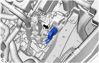
CHECK CONNECTOR CONNECTION CONDITION (INVERTER WITH CONVERTER ASSEMBLY CONNECTOR)
Result Result Proceed to OK A NG (The connector is not connected securely.) B NG (The terminals are not making secure contact or are deformed, or water or foreign matter exists in the connector.) C CAUTION:
Be sure to wear insulated gloves.
-
Check that the service plug grip is not installed.
Note
After removing the service plug grip, do not turn the power switch on (READY), unless instructed by the repair manual because this may cause a malfunction.
-
Check the connection condition of the low voltage connectors of the inverter with converter assembly and the contact pressure of each terminal. Check the terminals for deformation, and the connector for water and foreign matter.
Note
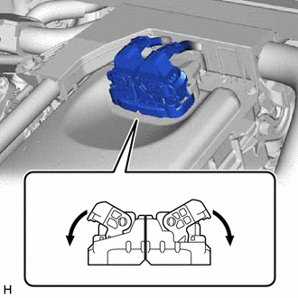
Before disconnecting the connector, confirm that it is properly connected by checking that the claws of the lock levers are engaged and that the connector cannot be pulled off.
OK - The connector is connected securely. - The terminals are not deformed and are connected securely. - No water or foreign matter in the connector. Result Result Proceed to OK A NG (The connector is not connected securely.) B NG (The terminals are not making secure contact or are deformed, or water or foreign matter exists in the connector.) C Tech Tips
When connecting the connector, connect it with the lock levers raised. Rotate each lock lever downward and make sure that the connector is securely connected. When a lock lever is fully lowered, a click will be heard as its claw engages. After the click is heard, pull up on the connector to confirm that it is securely connected.
B
CONNECT SECURELY
C
REPAIR OR REPLACE HARNESS OR CONNECTOR
A
-
-
CHECK HARNESS AND CONNECTOR (INVERTER WITH CONVERTER ASSEMBLY - GENERATOR RESOLVER)
CAUTION:
Be sure to wear insulated gloves.
-
Check that the service plug grip is not installed.
Note
After removing the service plug grip, do not turn the power switch on (READY), unless instructed by the repair manual because this may cause a malfunction.
-
Disconnect the C64 inverter with converter assembly connector.
-
Connect the cable to the negative (-) auxiliary battery terminal.
-
Turn the power switch on (IG).
-
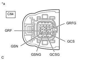
*a Front view of wire harness connector
(to Inverter with Converter Assembly)
Measure the voltage according to the value(s) in the table below.
Standard Voltage Tester Connection Condition Specified Condition C64-8 (GRF) - Body ground Power switch on (IG) Below 1 V C64-9 (GRFG) - Body ground Power switch on (IG) Below 1 V C64-10 (GSN) - Body ground Power switch on (IG) Below 1 V C64-11 (GSNG) - Body ground Power switch on (IG) Below 1 V C64-13 (GCS) - Body ground Power switch on (IG) Below 1 V C64-12 (GCSG) - Body ground Power switch on (IG) Below 1 V Note
Turning the power switch on (IG) with the inverter with converter assembly disconnected causes other DTCs to be stored. Clear the DTCs after performing this inspection.
-
Turn the power switch off.
-
Disconnect the cable from the negative (-) auxiliary battery terminal.
-
Reconnect the C64 inverter with converter assembly connector and wait for 2 minutes or more.
Result Proceed to OK NG
NG
REPAIR OR REPLACE HARNESS OR CONNECTOR
OK
-
-
CHECK GENERATOR RESOLVER
CAUTION:
Be sure to wear insulated gloves.
-
Check that the service plug grip is not installed.
Note
After removing the service plug grip, do not turn the power switch on (READY), unless instructed by the repair manual because this may cause a malfunction.
-
Disconnect the C64 inverter with converter assembly connector.
-

*a Front view of wire harness connector
(to Inverter with Converter Assembly)
Measure the resistance according to the value(s) in the table below.
Standard Resistance (Check for Open) Tester Connection Condition Specified Condition C64-8 (GRF) - C64-9 (GRFG) Power switch off 8.9 to 14.8 Ω C64-10 (GSN) - C64-11 (GSNG) Power switch off 22.6 to 34.5 Ω C64-13 (GCS) - C64-12 (GCSG) Power switch off 25.5 to 37.4 Ω Tech Tips
To correct the variation of the measured resistance due to temperature, use the following formula to calculate the resistance at 20°C (68°F).
R20 = Rt / {1 + 0.00393 X (T - 20)}
The calculation is based on the following:
R20: Resistance at 20°C (68°F) (mΩ)
Rt: Measured resistance (mΩ)
T: Temperature when the resistance is measured (°C (°F).)
Standard Resistance (Check for Short) Tester Connection Condition Specified Condition C64-8 (GRF) or C64-9 (GRFG)) - Body ground and other terminals Power switch off 1 MΩ or higher C64-10 (GSN) or C64-11 (GSNG) - Body ground and other terminals Power switch off 1 MΩ or higher C64-13 (GCS) or C64-12 (GCSG) - Body ground and other terminals Power switch off 1 MΩ or higher -
Reconnect the C64 inverter with converter assembly connector.
Result Proceed to OK NG
NG 
CHECK CONNECTOR CONNECTION CONDITION (RESOLVER CONNECTOR) Click here
OK
-
-
CHECK HARNESS AND CONNECTOR (INVERTER WITH CONVERTER ASSEMBLY - MOTOR RESOLVER)
CAUTION:
Be sure to wear insulated gloves.
-
Check that the service plug grip is not installed.
Note
After removing the service plug grip, do not turn the power switch on (READY), unless instructed by the repair manual because this may cause a malfunction.
-
Disconnect the C64 inverter with converter assembly connector.
-
Connect the cable to the negative (-) auxiliary battery terminal.
-
Turn the power switch on (IG).
-
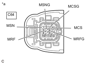
*a Front view of wire harness connector
(to Inverter with Converter Assembly)
Measure the voltage according to the value(s) in the table below.
Standard Voltage Tester Connection Condition Specified Condition C64-5 (MRF) - Body ground Power switch on (IG) Below 1 V C64-6 (MRFG) - Body ground Power switch on (IG) Below 1 V C64-1 (MSN) - Body ground Power switch on (IG) Below 1 V C64-2 (MSNG) - Body ground Power switch on (IG) Below 1 V C64-4 (MCS) - Body ground Power switch on (IG) Below 1 V C64-3 (MCSG) - Body ground Power switch on (IG) Below 1 V Note
Turning the power switch on (IG) with the inverter with converter assembly disconnected causes other DTCs to be stored. Clear the DTCs after performing this inspection.
-
Turn the power switch off.
-
Disconnect the cable from the negative (-) auxiliary battery terminal.
-
Reconnect the C64 inverter with converter assembly connector and wait for 2 minutes or more.
Result Proceed to OK NG
NG
REPAIR OR REPLACE HARNESS OR CONNECTOR
OK
-
-
CHECK MOTOR RESOLVER
CAUTION:
Be sure to wear insulated gloves.
-
Check that the service plug grip is not installed.
Note
After removing the service plug grip, do not turn the power switch on (READY), unless instructed by the repair manual because this may cause a malfunction.
-
Disconnect the C64 inverter with converter assembly connector.
-

*a Front view of wire harness connector
(to Inverter with Converter Assembly)
Measure the resistance according to the value(s) in the table below.
Standard Resistance (Check for Open) Tester Connection Condition Specified Condition C64-5 (MRF) - C64-6 (MRFG) Power switch off 8.9 to 14.9 Ω C64-1 (MSN) - C64-2 (MSNG) Power switch off 16.2 to 28.1 Ω C64-4 (MCS) - C64-3 (MCSG) Power switch off 18.2 to 30.1 Ω Tech Tips
To correct the variation of the measured resistance due to temperature, use the following formula to calculate the resistance at 20°C (68°F).
R20 = Rt / {1 + 0.00393 X (T - 20)}
The calculation is based on the following:
R20: Resistance at 20°C (68°F) (mΩ)
Rt: Measured resistance (mΩ)
T: Temperature when the resistance is measured (°C (°F).)
Standard Resistance (Check for Short) Tester Connection Condition Specified Condition C64-5 (MRF) or C64-6 (MRFG) - Body ground and other terminals Power switch off 1 MΩ or higher C64-1 (MSN) or C64-2 (MSNG) - Body ground and other terminals Power switch off 1 MΩ or higher C64-4 (MCS) or C64-3 (MCSG) - Body ground and other terminals Power switch off 1 MΩ or higher -
Reconnect the C64 inverter with converter assembly connector.
Result Proceed to OK NG
NG
CHECK CONNECTOR CONNECTION CONDITION (RESOLVER CONNECTOR) Click here
OK
-
-
CHECK CONNECTOR CONNECTION CONDITION (RESOLVER CONNECTOR)
-
Check the connection condition of the resolver connector and the contact pressure of each terminal. Check the terminals for deformation the connector for water and foreign matter.
OK - The connector is connected securely. - The terminals are not deformed and are connected securely. - No water or foreign matter in the connector. Result Result Proceed to OK A NG (The connector is not connected securely.) B NG (The terminals are not making secure contact or are deformed, or water or foreign matter exists in the connector.) C
A
REFER TO REPLACE INVERTER WITH CONVERTER ASSEMBLY PARTS Click here
B
CONNECT SECURELY
C
REPAIR OR REPLACE HARNESS OR CONNECTOR
-
-
CHECK CONNECTOR CONNECTION CONDITION (RESOLVER CONNECTOR)
-
Check the connection condition of the resolver connector and the contact pressure of each terminal. Check the terminals for deformation the connector for water and foreign matter.
OK - The connector is connected securely. - The terminals are not deformed and are connected securely. - No water or foreign matter in the connector. Result Result Proceed to OK A NG (The connector is not connected securely.) B NG (The terminals are not making secure contact or are deformed, or water or foreign matter exists in the connector.) C
B
CONNECT SECURELY
C
REPAIR OR REPLACE HARNESS OR CONNECTOR
A
-
-
CHECK HARNESS AND CONNECTOR (INVERTER WITH CONVERTER ASSEMBLY - GENERATOR RESOLVER)
CAUTION:
Be sure to wear insulated gloves.
-
Check that the service plug grip is not installed.
Note
After removing the service plug grip, do not turn the power switch on (READY), unless instructed by the repair manual because this may cause a malfunction.
-
Disconnect the C64 inverter with converter assembly connector.
-
Disconnect the C1 resolver connector.
-
Measure the resistance according to the value(s) in the table below.
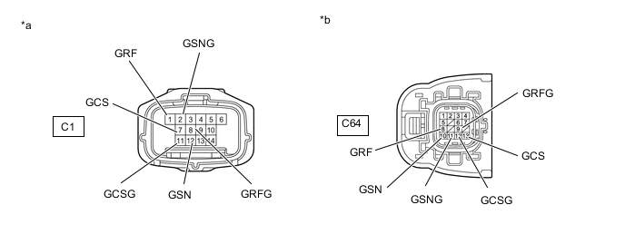
*a Front view of wire harness connector
(to Resolver)
*b Front view of wire harness connector
(to Inverter with Converter Assembly)
Standard Resistance (Check for Open) Tester Connection Condition Specified Condition C64-8 (GRF) - C1-1 (GRF) Power switch off Below 1 Ω C64-9 (GRFG) - C1-8 (GRFG) Power switch off Below 1 Ω C64-10 (GSN) - C1-12 (GSN) Power switch off Below 1 Ω C64-11 (GSNG) - C1-2 (GSNG) Power switch off Below 1 Ω C64-13 (GCS) - C1-7 (GCS) Power switch off Below 1 Ω C64-12 (GCSG) - C1-11 (GCSG) Power switch off Below 1 Ω Standard Resistance (Check for Short) Tester Connection Condition Specified Condition C64-8 (GRF) or C1-1 (GRF) - Body ground and other terminals Power switch off 1 MΩ or higher C64-9 (GRFG) or C1-8 (GRFG) - Body ground and other terminals Power switch off 1 MΩ or higher C64-10 (GSN) or C1-12 (GSN) - Body ground and other terminals Power switch off 1 MΩ or higher C64-11 (GSNG) or C1-2 (GSNG) - Body ground and other terminals Power switch off 1 MΩ or higher C64-13 (GCS) or C1-7 (GCS) - Body ground and other terminals Power switch off 1 MΩ or higher C64-12 (GCSG) or C1-11 (GCSG) - Body ground and other terminals Power switch off 1 MΩ or higher -
Reconnect the C1 resolver connector.
-
Reconnect the C64 inverter with converter assembly connector.
Result Proceed to OK NG
OK
REPLACE HYBRID VEHICLE TRANSAXLE ASSEMBLY Click here
NG
REPAIR OR REPLACE HARNESS OR CONNECTOR
-
-
CHECK CONNECTOR CONNECTION CONDITION (RESOLVER CONNECTOR)
-
Check the connection condition of the resolver connector and the contact pressure of each terminal. Check the terminals for deformation the connector for water and foreign matter.
OK - The connector is connected securely. - The terminals are not deformed and are connected securely. - No water or foreign matter in the connector. Result Result Proceed to OK A NG (The connector is not connected securely.) B NG (The terminals are not making secure contact or are deformed, or water or foreign matter exists in the connector.) C
B
CONNECT SECURELY
C
REPAIR OR REPLACE HARNESS OR CONNECTOR
A
-
-
CHECK HARNESS AND CONNECTOR (INVERTER WITH CONVERTER ASSEMBLY - MOTOR RESOLVER)
CAUTION:
Be sure to wear insulated gloves.
-
Check that the service plug grip is not installed.
Note
After removing the service plug grip, do not turn the power switch on (READY), unless instructed by the repair manual because this may cause a malfunction.
-
Disconnect the C64 inverter with converter assembly connector.
-
Disconnect the C1 resolver connector.
-
Measure the resistance according to the value(s) in the table below.
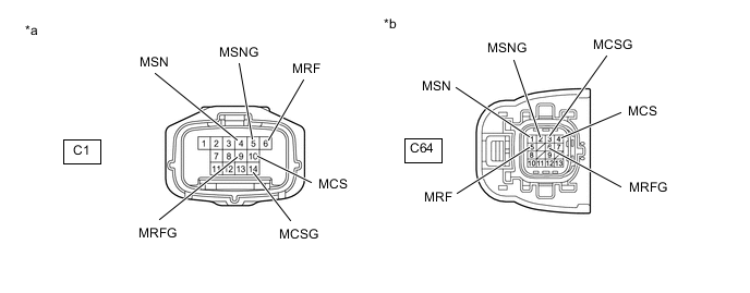
*a Front view of wire harness connector
(to Resolver)
*b Front view of wire harness connector
(to Inverter with Converter Assembly)
Standard Resistance (Check for Open) Tester Connection Condition Specified Condition C64-5 (MRF) - C1-6 (MRF) Power switch off Below 1 Ω C64-6 (MRFG) - C1-9 (MRFG) Power switch off Below 1 Ω C64-1 (MSN) - C1-4 (MSN) Power switch off Below 1 Ω C64-2 (MSNG) - C1-5 (MSNG) Power switch off Below 1 Ω C64-4 (MCS) - C1-10 (MCS) Power switch off Below 1 Ω C64-3 (MCSG) - C1-14 (MCSG) Power switch off Below 1 Ω Standard Resistance (Check for Short) Tester Connection Condition Specified Condition C64-5 (MRF) or C1-6 (MRF) - Body ground and other terminals Power switch off 1 MΩ or higher C64-6 (MRFG) or C1-9 (MRFG) - Body ground and other terminals Power switch off 1 MΩ or higher C64-1 (MSN) or C1-4 (MSN) - Body ground and other terminals Power switch off 1 MΩ or higher C64-2 (MSNG) or C1-5 (MSNG) - Body ground and other terminals Power switch off 1 MΩ or higher C64-4 (MCS) or C1-10 (MCS) - Body ground and other terminals Power switch off 1 MΩ or higher C64-3 (MCSG) or C1-14 (MCSG) - Body ground and other terminals Power switch off 1 MΩ or higher -
Reconnect the C1 resolver connector.
-
Reconnect the C64 inverter with converter assembly connector.
Result Proceed to OK NG
OK
REPLACE HYBRID VEHICLE TRANSAXLE ASSEMBLY Click here
NG
REPAIR OR REPLACE HARNESS OR CONNECTOR
-