HYBRID CONTROL SYSTEM, Diagnostic DTC:P1CFA12
| DTC Code | DTC Name |
|---|---|
| P1CFA12 | IGB Signal Circuit Short to Auxiliary Battery |
DESCRIPTION
The hybrid vehicle control ECU monitors the IGB signal received from the certification ECU (smart key ECU assembly). When an error is detected in the ST signal, this DTC is stored.
| DTC No. | Detection Item | DTC Detection Condition | Trouble Area | MIL | Warning Indicate |
|---|---|---|---|---|---|
| P1CFA12 | IGB Signal Circuit Short to Auxiliary Battery | An IGB signal from the hybrid vehicle control ECU is on when the power switch is off. (1 trip detection logic) |
|
Does not come on | Master Warning Light: Comes on |
CONFIRMATION DRIVING PATTERN
Tech Tips
After repairs have been completed, clear the DTCs and then check that the vehicle has returned to normal by performing the following All Readiness check procedure.
-
Connect the GTS to the DLC3.
-
Turn the power switch on (IG) and turn the GTS on.
-
Clear the DTCs (even if no DTCs are stored, perform the clear DTC procedure).
-
Turn the power switch off and wait for 2 minutes or more.
-
Turn the power switch on (IG) and turn the GTS on.
-
Enter the following menus: Powertrain / Hybrid Control / Utility / All Readiness.
-
Check the DTC judgment result.
Tech Tips
-
If the judgment result shows NORMAL, the system is normal.
-
If the judgment result shows ABNORMAL, the system has a malfunction.
-
If the judgment result shows INCOMPLETE or N/A, perform driving pattern again.
-
WIRING DIAGRAM
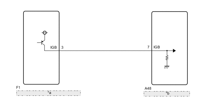
| *a | Certification ECU (Smart Key ECU Assembly) |
| *b | Hybrid Vehicle Control ECU |
CAUTION / NOTICE / HINT
Note
Before replacing the certification ECU (smart key ECU assembly), refer to Service Bulletin.
PROCEDURE
-
CHECK CONNECTOR CONNECTION CONDITION (HYBRID VEHICLE CONTROL ECU CONNECTOR)
Result Proceed to OK NG
-
Check the connector connections and contact pressure of the relevant terminals for the hybrid vehicle control ECU connectors.
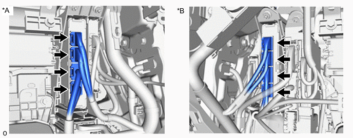
*A for LHD *B for RHD OK The connectors are connected securely and there are no contact pressure problems. Result Proceed to OK NG
NG 
CONNECT SECURELY
OK 
-
-
CHECK CONNECTOR CONNECTION CONDITION (CERTIFICATION ECU [SMART KEY ECU ASSEMBLY])
-
Check the connector connection condition of the certification ECU (smart key ECU assembly).
OK The connector is connected securely and there are no contact problems. Result Proceed to OK NG
NG
CONNECT SECURELY
OK
-
-
CHECK HARNESS AND CONNECTOR (IGB TERMINAL VOLTAGE)
-
Turn the power switch off.
-
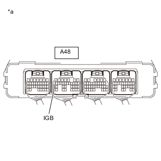
*a Component with harness connected
(Hybrid Vehicle Control ECU)
Measure the voltage according to the value(s) in the table below.
Standard Voltage Tester Connection Condition Specified Condition A48-7 (IGB) - Body ground Power switch off Below 1 V Result Proceed to OK NG
OK
REPLACE HYBRID VEHICLE CONTROL ECU Click here
NG
-
-
CHECK HARNESS AND CONNECTOR (HYBRID VEHICLE CONTROL ECU - CERTIFICATION ECU [SMART KEY ECU ASSEMBLY])
-
Disconnect the F1 certification ECU (smart key ECU assembly) connector.
-
*a Component with harness connected
(Hybrid Vehicle Control ECU)
Measure the voltage according to the value(s) in the table below.
Standard Voltage Tester Connection Condition Specified Condition A48-7 (IGB) - Body ground Power switch off Below 1 V -
Reconnect the F1 certification ECU (smart key ECU assembly) connector.
Result Proceed to OK NG
OK
REPLACE CERTIFICATION ECU (SMART KEY ECU ASSEMBLY)
NG
REPAIR OR REPLACE HARNESS OR CONNECTOR
-