HYBRID CONTROL SYSTEM, Diagnostic DTC:P0ABF00
| DTC Code | DTC Name |
|---|---|
| P0ABF00 | Hybrid/EV Battery Current Sensor "A" Circuit Range/Performance |
DESCRIPTION
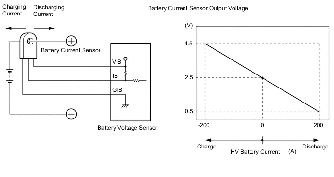
A battery current sensor is installed to the positive (+) terminal side of the HV battery and detects current flowing from the HV battery. The battery current sensor outputs voltage, which changes between 0 and 5 V according to the detected amperage, to the IB terminal of the battery voltage sensor. The battery voltage sensor sends signals to the hybrid vehicle control ECU. The hybrid vehicle control ECU determines the charging and discharging amount of the HV battery based on the received signals and calculates the SOC of the HV battery through the accumulated amperage.
| DTC No. | Detection Item | DTC Detection Condition | Trouble Area | MIL | Warning Indicate |
|---|---|---|---|---|---|
| P0ABF00 | Hybrid/EV Battery Current Sensor "A" Circuit Range/Performance | Abnormal battery current sensor characteristics: (based on hybrid system consumption and HV battery output). (1 trip detection logic) |
|
Comes on | Master Warning Light: Comes on |
| DTC No. | Data List |
|---|---|
| P0ABF00 | - |
CONFIRMATION DRIVING PATTERN
Tech Tips
After repair has been completed, clear the DTC and then check that the vehicle has returned to normal by performing the following All Readiness check procedure.
-
Connect the GTS to the DLC3.
-
Turn the power switch on (IG) and turn the GTS on.
-
Clear the DTCs (even if no DTCs are stored, perform the clear DTC procedure).
-
Turn the power switch off and wait for 2 minutes or more.
-
Turn the power switch on (IG) and turn the GTS on.
-
Drive the vehicle for approximately 10 minutes according to the freeze frame data items "Vehicle Speed", "Accelerator Position", "Hybrid Battery Current", "Motor Torque" and "Generator Torque".
-
Enter the following menus: Powertrain / Hybrid Control / Utility / All Readiness.
-
Check the DTC judgment result.
Tech Tips
-
If the judgment result shows NORMAL, the system is normal.
-
If the judgment result shows ABNORMAL, the system has a malfunction.
-
If the judgment result shows INCOMPLETE or N/A, perform driving pattern again.
-
PROCEDURE
-
CHECK DTC OUTPUT (HYBRID CONTROL)
-
Connect the GTS to the DLC3.
-
Turn the power switch on (IG).
-
Enter the following menus: Powertrain / Hybrid Control / Trouble Codes.
-
Check for DTCs.
Powertrain > Hybrid Control > Trouble CodesResult Result Proceed to One of the following applies:
-
Only P0ABF00 is output.
-
One or more DTCs other than P0AFC00 and P0AFC96 are also output.
A P0AFC00 or P0AFC96 is also output. B -
-
Turn the power switch off.
-
Disconnect the GTS from the DLC3.
B 
GO TO DTC CHART (HYBRID CONTROL SYSTEM) Click here
A 
-
-
CHECK HARNESS AND CONNECTOR (BATTERY VOLTAGE SENSOR - HV BATTERY JUNCTION BLOCK ASSEMBLY)
Result Proceed to OK NG CAUTION:
Be sure to wear insulated gloves.
-
Check that the service plug grip is not installed.
Note
After removing the service plug grip, do not turn the power switch on (READY), unless instructed by the repair manual because this may cause a malfunction.
-
Remove the No. 1 HV battery cover panel RH.
-
Disconnect the battery current sensor connector from the HV battery junction block assembly.
Note
Before disconnecting the connector, check that it is not loose or disconnected.
-
Remove the No. 1 hybrid battery exhaust duct.
-
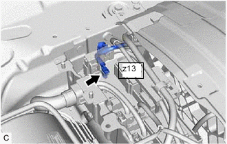
Disconnect the battery voltage sensor connector.
Note
Before disconnecting the connector, check that it is not loose or disconnected.
-
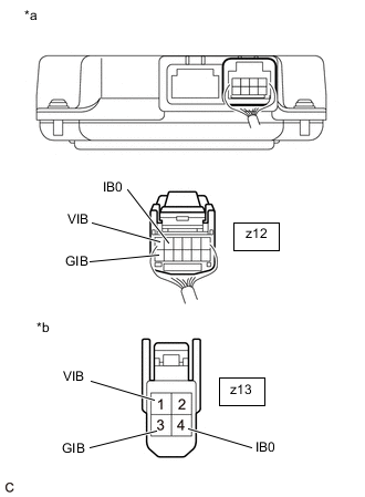
*a Rear view of wire harness connector
(to Battery Voltage Sensor)
*b Front view of wire harness connector
(to HV Battery Junction Block Assembly (Battery Current Sensor))
Measure the resistance according to the value(s) in the tables below.
Standard Resistance (Check for Open) Tester Connection Condition Specified Condition z12-5 (IB0) - z13-4 (IB0) Power switch off Below 1 Ω z12-12 (GIB) - z13-3 (GIB) Power switch off Below 1 Ω z12-6 (VIB) - z13-1 (VIB) Power switch off Below 1 Ω Standard Resistance (Check for Short) Tester Connection Condition Specified Condition z12-5 (IB0) or z13-4 (IB0) - Body ground and other terminals Power switch off 10 kΩ or higher z12-12 (GIB) or z13-3 (GIB) - Body ground and other terminals Power switch off 10 kΩ or higher z12-6 (VIB) or z13-1 (VIB) - Body ground and other terminals Power switch off 10 kΩ or higher Tech Tips
As the battery harness is not available as a supply part, if the harness cannot be repaired, replace the HV battery.
-
Reconnect the battery voltage sensor connector.
-
Install the No. 1 hybrid battery exhaust duct.
-
Reconnect the battery current sensor connector to the HV battery junction block assembly.
-
Install the No. 1 HV battery cover panel RH.
Result Proceed to OK NG
NG
REPLACE HYBRID BATTERY THERMISTOR Click here
OK
-
-
REPLACE HV BATTERY JUNCTION BLOCK ASSEMBLY
Result Proceed to NEXT
NEXT
-
CLEAR DTC
Result Proceed to NEXT
-
Connect the GTS to the DLC3.
-
Turn the power switch on (IG).
-
Enter the following menus: Powertrain / Hybrid Control / Trouble Codes.
-
Read and record the DTCs and freeze frame data.
Powertrain > Hybrid Control > Trouble Codes -
Clear the DTCs and freeze frame data.
Powertrain > Hybrid Control > Clear DTCs -
Turn the power switch off.
Result Proceed to NEXT
NEXT
-
-
PERFORM ROAD TEST
-
Drive the vehicle for approximately 10 minutes according to the freeze frame data items "Vehicle Speed", "Accelerator Position", "Hybrid Battery Current", "Motor Torque" and "Generated Torque".
CAUTION:
When performing the confirmation driving pattern, obey all speed limits and traffic laws.
Result Proceed to NEXT
NEXT
-
-
CHECK DTC OUTPUT (HYBRID CONTROL)
-
Connect the GTS to the DLC3.
-
Turn the power switch on (IG).
-
Enter the following menus: Powertrain / Hybrid Control / Trouble Codes.
-
Check for DTCs.
Powertrain > Hybrid Control > Trouble CodesResult Result Proceed to P0ABF00 is not output. A P0ABF00 is output again. B -
Turn the power switch off.
A
COMPLETED
B
REPLACE BATTERY VOLTAGE SENSOR Click here
-