LIGHTING SYSTEM TERMINALS OF ECU
-
CHECK INSTRUMENT PANEL JUNCTION BLOCK ASSEMBLY AND MAIN BODY ECU (MULTIPLEX NETWORK BODY ECU)
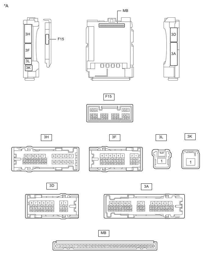
*A Main Body ECU (Multiplex Network Body ECU) with 1 Connector - - 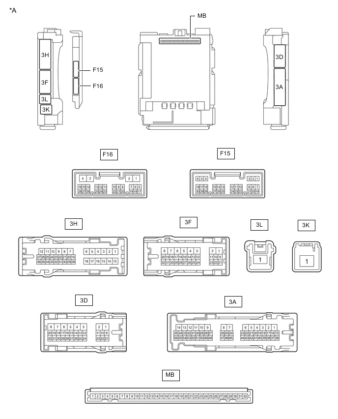
*A Main Body ECU (Multiplex Network Body ECU) with 2 Connectors - -
-
Disconnect the instrument panel junction block assembly and main body ECU (multiplex network body ECU) connectors.
-
Measure the voltage and resistance according to the value(s) in the table below.
Terminal No. (Symbol) Wiring Color Terminal Description Condition Specified Condition 3F-1 - Body ground W - Body ground Auxiliary battery power supply Power switch off 11 to 14 V 3K-1 - Body ground B-R - Body ground Auxiliary battery power supply Power switch off 11 to 14 V 3D-3 - Body ground W-B - Body ground Ground Always Below 1 Ω If the result is not as specified, there may be a malfunction in the wire harness.
-
Reconnect the instrument panel junction block assembly and main body ECU (multiplex network body ECU) connectors.
-
Measure the voltage and check for pulses according to the value(s) in the table below.
Terminal No. (Symbol) Wiring Color Terminal Description Condition Specified Condition 3A-30 - Body ground LG - Body ground ACC power supply Power switch on (ACC) 11 to 14 V Power switch off Below 1 V 3A-17 - Body ground GR - Body ground IG power supply Power switch on (IG) 11 to 14 V Power switch off Below 1 V 3D-24*2 - Body ground L - Body ground Door ambient illumination light RH power supply Power switch off 11 to 14 V 3D-25*2 - Body ground G - Body ground Door ambient illumination light LH power supply Power switch off 11 to 14 V 3D-26*2 - Body ground P - Body ground No. 1 cup holder illumination light power supply Power switch off 11 to 14 V 3D-27*2 - Body ground R - Body ground No. 2 cup holder illumination light power supply Power switch off 11 to 14 V 3H-19 - Body ground L - Body ground No. 1 luggage compartment light power supply DOME CUT relay on 11 to 14 V DOME CUT relay off Below 1 V 3D-9 - Body ground W - Body ground Map light assembly, No. 1 room light and vanity lights power supply DOME CUT relay on 11 to 14 V DOME CUT relay off Below 1 V 3D-29 - Body ground G - Body ground Interior lights drive output Interior lights off (when operated by illuminated entry system) 11 to 14 V Interior lights on (when operated by illuminated entry system) Below 1 V 3H-24 - Body ground BR - Body ground Rear door courtesy light switch LH input Rear door LH open Below 1 V Rear door LH closed Pulse generation 3A-31 - Body ground BR - Body ground Rear door courtesy light switch RH input Rear door RH open Below 1 V Rear door RH closed Pulse generation F15-6 (FLCY) - Body ground R - Body ground Front door courtesy light switch LH input Front door LH open Below 1 V Front door LH closed Pulse generation F15-27 (FRCY) - Body ground BR - Body ground Front door courtesy light switch RH input Front door RH open Below 1 V Front door RH closed Pulse generation 3D-14*1, *3 - Body ground LG - Body ground Rear door unlock detection switch input Rear door locked Pulse generation Rear door unlocked Below 1 V 3D-13 - Body ground B - Body ground Front door unlock detection switch LH input Front door LH locked Pulse generation Front door LH unlocked Below 1 V 3D-12 - Body ground GR - Body ground Front door unlock detection switch RH input Front door RH locked Pulse generation Front door RH unlocked Below 1 V F15-25 (BCYL) - Body ground Y - Body ground No. 1 luggage compartment light drive output No. 1 luggage compartment light off 11 to 14 V No. 1 luggage compartment light on Below 1 V 3H-34 - Body ground SB - Body ground Back door courtesy light switch input Back door open Below 1 V Back door closed 11 to 14 V If the result is not as specified, the main body ECU (multiplex network body ECU) or instrument panel junction block assembly may be malfunctioning.
*1: w/ Entry Function
*2: w/ Door Ambient Illumination Light
*3: w/ Double Locking System
-
-
CHECK CERTIFICATION ECU (SMART KEY ECU ASSEMBLY)
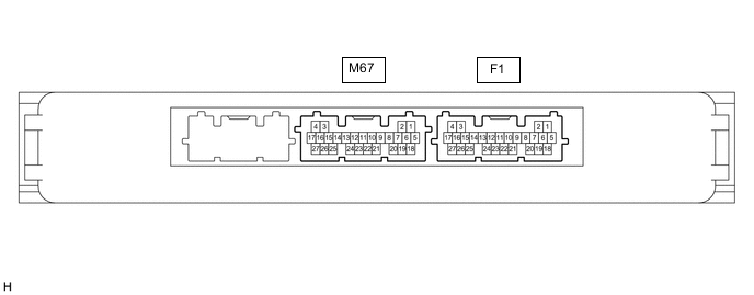
-
Measure the voltage according to the value(s) in the table below.
Terminal No. (Symbol) Wiring Color Terminal Description Condition Specified Condition F1-10 (SWIL) - F1-11 (AGND) LG - P Power switch illumination drive output Power switch illumination on 11 to 14 V Power switch illumination off Below 1 V
-
If the result is not as specified, the certification ECU (smart key ECU assembly) may be malfunctioning.
-
-