HYBRID CONTROL SYSTEM, Diagnostic DTC:P0A1B94
| DTC Code | DTC Name |
|---|---|
| P0A1B94 | Drive Motor "A" Control Module Unexpected Operation |
DTC SUMMARY
-
MALFUNCTION DESCRIPTION
The hybrid vehicle control ECU monitors the motor generator control ECU (MG ECU).
The cause of this malfunction may be the following:
-
Motor generator control ECU (MG ECU) malfunction
Motor generator control ECU internal malfunction
-
DESCRIPTION
The hybrid vehicle control ECU monitors the motor generator control ECU (MG ECU) and stores this DTC when it detects a malfunction.
| DTC No. | Detection Item | DTC Detection Condition | Trouble Area | MIL | Warning Indicate |
|---|---|---|---|---|---|
| P0A1B94 | Drive Motor "A" Control Module Unexpected Operation | The motor generator control ECU (MG ECU) value received by the hybrid vehicle control ECU exceeds the threshold for a certain period of time. (1 trip detection logic) |
|
Comes on | Master Warning Light: Comes on |
CONFIRMATION DRIVING PATTERN
Tech Tips
After repair has been completed, clear the DTC and then check that the vehicle has returned to normal by performing the following All Readiness check procedure.
-
Connect the GTS to the DLC3.
-
Turn the power switch on (IG) and turn the GTS on.
-
Clear the DTCs (even if no DTCs are stored, perform the clear DTC procedure).
-
Turn the power switch off and wait for 2 minutes or more.
-
Turn the power switch on (IG) and turn the GTS on.
-
With power switch on (IG) and wait for 2 minutes or more.
Tech Tips
If the vehicle has returned to normal, it can be driven after turning the power switch on (READY).
-
Enter the following menus: Powertrain / Hybrid Control / Utility / All Readiness.
-
Check the DTC judgment result.
Tech Tips
-
If the judgment result shows NORMAL, the system is normal.
-
If the judgment result shows ABNORMAL, the system has a malfunction.
-
If the judgment result shows INCOMPLETE or N/A, perform driving pattern again.
-
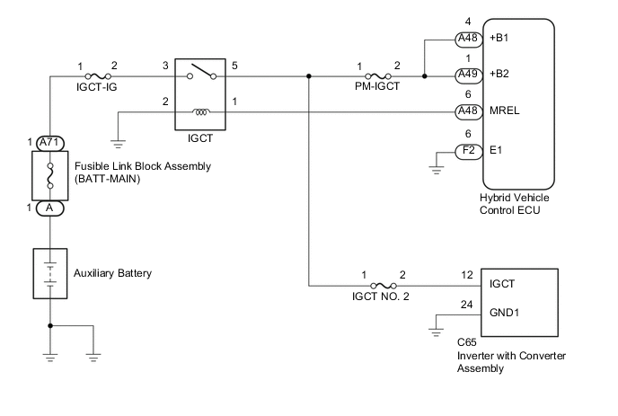
WIRING DIAGRAM
PROCEDURE
-
CHECK AUXILIARY BATTERY TERMINAL (CONTACT PROBLEM)
-
Check the connection of the negative (-) and positive (+) auxiliary battery terminals.
OK The terminals are connected securely and there is no contact problem. Tech Tips
If performing a reproduction test, turn the power switch on (IG) and shake the wire harnesses vertically and horizontally before checking for DTCs.
Result Proceed to OK NG
NG 
CONNECT SECURELY Click here
OK 
-
-
CHECK GROUND WIRE CONNECTION CONDITION
-
Check the installation condition of the ground wires DA and DC.
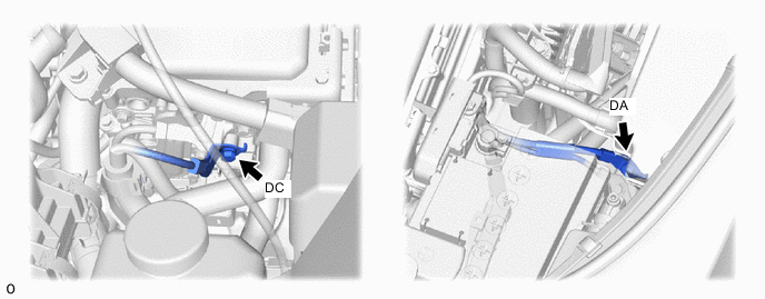
OK The ground wires DA and DC are securely installed. Tech Tips
If performing a reproduction test, turn the power switch on (IG) and shake the wire harnesses vertically and horizontally before checking for DTCs.
Result Proceed to OK NG
NG
CONNECT SECURELY Click here
OK
-
-
CHECK FUSIBLE LINK (BATT-MAIN)
-
Disconnect the cable from the negative (-) auxiliary battery terminal.
-
Disconnect the cable from the positive (+) auxiliary battery terminal.
-
Check the fusible link block assembly (BATT-MAIN) for improper installation.
OK The fusible link block assembly is installed securely and there is no contact problem. -
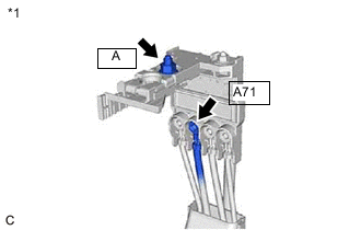
*1 Fusible Link Block Assembly Measure the resistance according to the value(s) in the table below.
Standard Resistance Tester Connection Condition Specified Condition A71-1 - A-1 (Positive (+) auxiliary battery terminal) Power switch off Below 1 Ω -
Reconnect the cable from the positive (+) auxiliary battery terminal.
-
Reconnect the cable from the negative (-) auxiliary battery terminal.
Result Proceed to OK NG
NG
REPAIR OR REPLACE MALFUNCTIONING PARTS Click here
OK
-
-
CHECK FUSE (IGCT-IG)
-
Check the IGCT-IG fuse for improper installation.
OK The fuse is installed securely. Tech Tips
If performing a reproduction test, turn the power switch on (IG) and gently vibrate the IGCT-IG fuse with a finger before checking for DTCs.
-
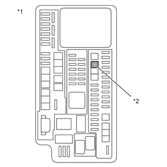
*1 No. 1 Engine Room Relay Block *2 IGCT-IG Fuse Remove the IGCT-IG fuse from the No. 1 engine room relay block.
-
Measure the resistance according to the value(s) in the table below.
Standard Resistance Tester Connection Condition Specified Condition IGCT-IG fuse Power switch off Below 1 Ω -
Install the IGCT-IG fuse to the No. 1 engine room relay block.
Result Proceed to OK NG
NG
REPAIR OR REPLACE MALFUNCTIONING PARTS Click here
OK
-
-
CHECK RELAY (IGCT)
-
Check the IGCT relay for improper installation.
OK The relay is installed securely. Tech Tips
If performing a reproduction test, turn the power switch on (IG) and gently vibrate the IGCT relay with a finger before checking for DTCs.
-
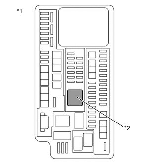
*1 No. 1 Engine Room Relay Block *2 IGCT Relay Remove the IGCT relay from the No. 1 engine room relay block.
-
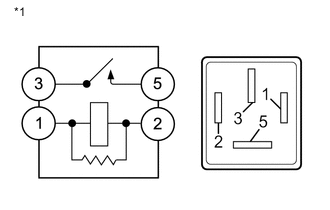
*1 IGCT Relay Measure the resistance according to the value(s) in the table below.
Standard Resistance Tester Connection Condition Specified Condition 3 - 5 Auxiliary battery voltage not applied between terminals 1 and 2 10 kΩ or higher Auxiliary battery voltage applied between terminals 1 and 2 Below 1 Ω -
Install the IGCT relay.
Result Proceed to OK NG
NG
REPAIR OR REPLACE MALFUNCTIONING PARTS Click here
OK
-
-
CHECK DTC OUTPUT (HYBRID CONTROL)
-
Connect the GTS to the DLC3.
-
Turn the power switch on (IG).
-
Enter the following menus: Powertrain / Hybrid Control / Trouble Codes.
-
Check for DTCs.
Tech Tips
Check the DTCs that were output when the vehicle was brought to the workshop.
Powertrain > Hybrid Control > Trouble CodesResult Result Proceed to P0A1B94 only is output. A DTCs except P0A1B94 are output. B -
Turn the power switch off.
A 
REFER TO REPLACE INVERTER WITH CONVERTER ASSEMBLY PARTS Click here
B
GO TO DTC CHART (HYBRID CONTROL SYSTEM) Click here
-
-
CONNECT SECURELY
Result Proceed to NEXT
NEXT
GO TO STEP 12 Click here
-
CONNECT SECURELY
Result Proceed to NEXT
NEXT
GO TO STEP 12 Click here
-
REPAIR OR REPLACE MALFUNCTIONING PARTS
Result Proceed to NEXT
NEXT
GO TO STEP 12 Click here
-
REPAIR OR REPLACE MALFUNCTIONING PARTS
Result Proceed to NEXT
NEXT
GO TO STEP 12 Click here
-
REPAIR OR REPLACE MALFUNCTIONING PARTS
Result Proceed to NEXT
NEXT
-
CLEAR DTC
Result Proceed to NEXT
-
Connect the GTS to the DLC3.
-
Turn the power switch on (IG).
-
Enter the following menus: Powertrain / Hybrid Control / Trouble Codes.
-
Read and record the DTCs and freeze frame data.
Powertrain > Hybrid Control > Trouble Codes -
Clear the DTCs and freeze frame data.
Powertrain > Hybrid Control > Clear DTCs -
Turn the power switch off.
Result Proceed to NEXT
NEXT
-
-
SIMULATION TEST
-
Turn the power switch off and wait for 2 minutes or more.
-
Turn the power switch on (IG) and wait for 2 minutes or more.
-
Turn the power switch off.
Result Proceed to NEXT
NEXT
-
-
CHECK DTC OUTPUT (HYBRID CONTROL)
-
Connect the GTS to the DLC3.
-
Turn the power switch on (IG).
-
Enter the following menus: Powertrain / Hybrid Control / Trouble Codes.
-
Check for DTCs.
Powertrain > Hybrid Control > Trouble CodesResult Result Proceed to No DTCs are output. A P0A1B94 only is output. B DTCs except P0A1B94 are output. C -
Turn the power switch off.
A
END
B
REFER TO REPLACE INVERTER WITH CONVERTER ASSEMBLY PARTS Click here
C
GO TO DTC CHART (HYBRID CONTROL SYSTEM) Click here
-