METER / GAUGE SYSTEM Tachometer Malfunction
DESCRIPTION
In this circuit, the combination meter assembly receives engine speed signals from the ECM using the CAN communication system. The combination meter assembly displays the engine speed calculated based on the data received from the ECM.
WIRING DIAGRAM
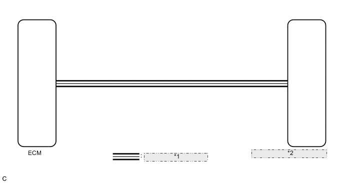
| *1 | CAN Communication Line |
| *2 | Combination Meter Assembly |
PROCEDURE
-
CHECK CAN COMMUNICATION SYSTEM
-
Check if CAN communication DTCs are output (See page w/ Central Gateway ECU, Click here w/o Central Gateway ECU).
Result Result Proceed to CAN communication DTCs are not output. A CAN communication DTCs are output (w/ Central Gateway ECU). B CAN communication DTCs are output (w/o Central Gateway ECU). C
B 
GO TO CAN COMMUNICATION SYSTEM Click here
C
GO TO CAN COMMUNICATION SYSTEM Click here
A 
-
-
PERFORM ACTIVE TEST USING GTS (TACHOMETER OPERATION)
-
Connect the GTS to the DLC3.
-
Turn the engine switch on (IG).
-
Turn the GTS on.
-
Enter the following menus: Body Electrical / Combination Meter / Active Test.
-
Perform the Active Test according to the display on the GTS.
Combination Meter Tester Display Test Part Control Range Diagnostic Note Tacho Meter Operation Tachometer OFF, 0, 1000, 2000, 3000, 4000, 5000, 6000, 7000 - OK Tachometer indication is normal.
NG
REPLACE COMBINATION METER ASSEMBLY Click here
OK
-
-
READ VALUE USING GTS (ENGINE RPM)
-
Connect the GTS to the DLC3.
-
Turn the engine switch on (IG).
-
Turn the GTS on.
-
Enter the following menus: Body Electrical / Combination Meter / Data List.
-
Read the Data List according to the display on the GTS.
Combination Meter Tester Display Measurement Item/Range Normal Condition Diagnostic Note Engine Rpm Engine speed/Min.: 0 rpm, Max.: 12750 rpm Almost the same as actual engine speed - OK Engine speed displayed on the GTS is almost the same as the tachometer indication. Tech Tips
-
When the Data List values and tachometer values match, a signal output error of the ECM or an internal malfunction of the combination meter assembly is suspected.
-
When the Data List values and tachometer values do not match, an internal malfunction of the combination meter assembly is suspected.
-
NG
REPLACE COMBINATION METER ASSEMBLY Click here
OK
-
-
CHECK SFI SYSTEM
-
Check if SFI system DTCs are output (See page for 2AR-FE, for 2GR-FE, Click here for 6AR-FSE).
Result Result Proceed to DTCs are not output. A DTCs are output (for 2AR-FE). B DTCs are output (for 2GR-FE). C DTCs are output (for 6AR-FSE). D
B
GO TO SFI SYSTEM Click here
C
GO TO SFI SYSTEM Click here
D
GO TO SFI SYSTEM Click here
A
-
-
READ VALUE USING GTS (ENGINE SPEED, ENGINE RPM)
-
Connect the GTS to the DLC3.
-
Turn the engine switch on (IG).
-
Turn the GTS on.
-
Enter the following menus:
-
for Engine and ECT: Powertrain / Engine and ECT / Data List.
-
for Combination Meter: Body Electrical / Combination Meter / Data List.
-
-
Read the Data List according to the display on the GTS.
Engine and ECT Tester Display Measurement Item/Range Normal Condition Stored as Freeze Frame Data Engine Speed Engine speed/Min.: 0 rpm, Max.: 16383 rpm for 2AR-FE:
610 to 710 rpm: Idling
for 2GR-FE:
600 to 700 rpm: Idling
for 6AR-FSE:
600 to 700 rpm: Idling (shift lever in P, engine warmed up and A/C off)
Yes except 6AR-FSE:
Results of real-vehicle check:
Idling (engine warmed up and A/C off): 660 rpm
Diagnostic Note:
When the crankshaft position sensor is malfunctioning, "Engine Speed" is approximately 0 rpm or varies greatly from the actual engine speed.
Combination Meter Tester Display Measurement Item/Range Normal Condition Diagnostic Note Engine Rpm Engine speed/Min.: 0 rpm, Max.: 12750 rpm Almost the same as actual engine speed - Result Result Proceed to The data list values of the ECUs do not match. A The data list values of the ECUs match (for 2AR-FE). B The data list values of the ECUs match (for 2GR-FE). C The data list values of the ECUs match (for 6AR-FSE). D Tech Tips
-
When the Data List values of the ECUs match, an internal malfunction of the ECM is suspected.
-
When the Data List values of the ECUs do not match, a signal output error of the ECM or an internal malfunction of the combination meter assembly is suspected.
-
B
REPLACE ECM Click here
C
REPLACE ECM Click here
D
REPLACE ECM Click here
A
-
-
REPLACE COMBINATION METER ASSEMBLY
-
Replace the combination meter assembly with a new one Click here.
OK The operation of the tachometer returns to normal. Result Result Proceed to OK A NG (for 2AR-FE) B NG (for 2GR-FE) C NG (for 6AR-FSE) D
A
END
B
REPLACE ECM Click here
C
REPLACE ECM Click here
D
REPLACE ECM Click here
-