METER / GAUGE SYSTEM Entire Combination Meter does not Operate
DESCRIPTION
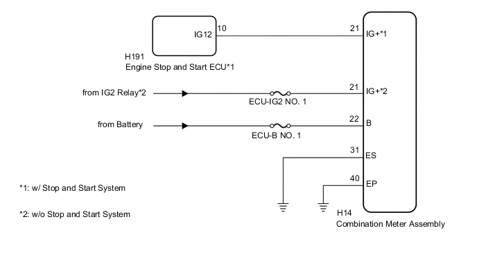
This circuit is the power source circuit for the meter. This circuit provides two types of power sources; one is a constant power source, and the other is an IG power source.
WIRING DIAGRAM
CAUTION / NOTICE / HINT
Note
Inspect the fuses of circuits related to this system before performing the following inspection procedure.
PROCEDURE
-
CONFIRM VEHICLE TYPE
-
Choose the model to be inspected.
Result Result Proceed to w/ Stop and Start System A w/o Stop and Start System B
B 
CHECK HARNESS AND CONNECTOR (COMBINATION METER ASSEMBLY CIRCUIT) Click here
A 
-
-
CHECK STOP AND START SYSTEM
-
Check the backup boost converter circuit Click here.
OK The operation of the combination meter assembly returns to normal.
OK 
END
NG
-
-
CHECK HARNESS AND CONNECTOR (COMBINATION METER ASSEMBLY CIRCUIT)
-
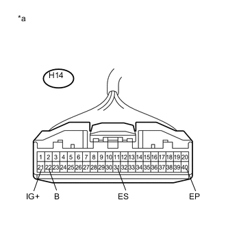
Text in Illustration *a Front view of wire harness connector
(to Combination Meter Assembly)
Disconnect the H14 combination meter assembly connector.
-
Measure the resistance according to the value(s) in the table below.
Standard Resistance Tester Connection Condition Specified Condition H14-31 (ES) - Body ground Always Below 1 Ω H14-40 (EP) - Body ground Always Below 1 Ω -
Measure the voltage according to the value(s) in the table below.
Standard Voltage Tester Connection Condition Specified Condition H14-21 (IG+) - Body ground* Ignition switch off Below 1 V Ignition switch ON 11 to 14 V H14-22 (B) - Body ground Always 11 to 14 V
-
*: w/o Stop and Start System
-
OK
REPLACE COMBINATION METER ASSEMBLY Click here
NG
REPAIR OR REPLACE HARNESS OR CONNECTOR
-