METER / GAUGE SYSTEM, Diagnostic DTC:B1507, B1508
| DTC Code | DTC Name |
|---|---|
| B1507 | Open in Turn Signal Circuit |
| B1508 | Short in Turn Signal / Hazard Flasher Circuit |
DESCRIPTION
These DTCs are stored when the combination meter assembly detects an open in a turn signal light circuit, a short in a turn signal light circuit, or a short in the hazard warning light circuit.
| DTC No. | DTC Detection Condition | Trouble Area |
|---|---|---|
| B1507 | When IG voltage is 9.5 V or more and the following condition is detected:
|
|
| B1508 | When IG voltage is 9.5 V or more and the following condition is detected:
|
|
-
*: w/ Reverse Shift-linked Mirror
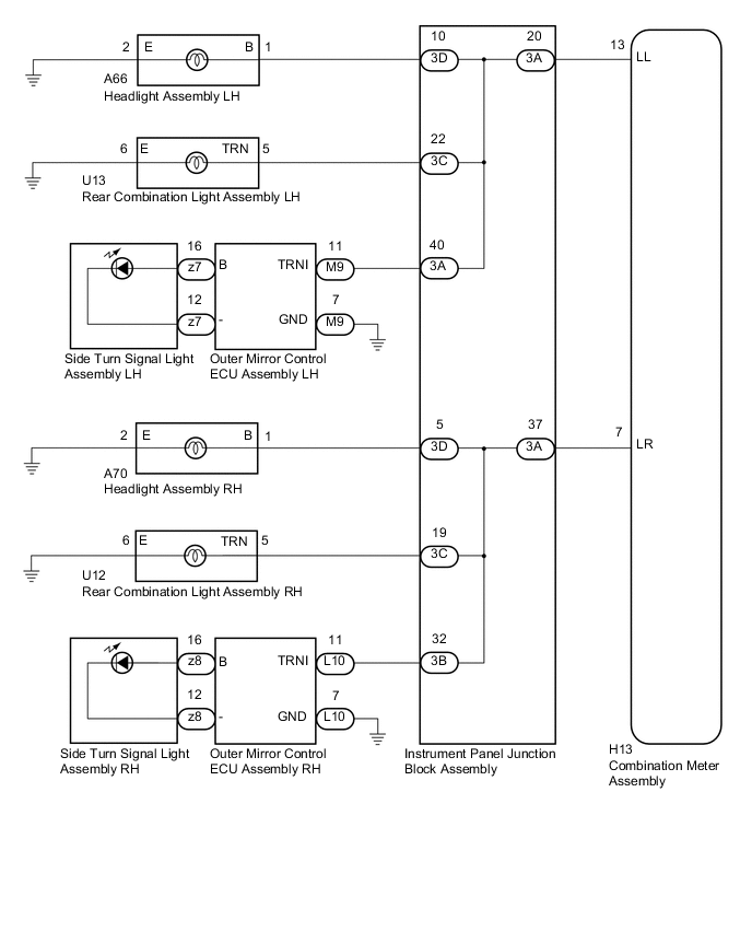
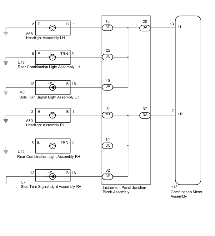
WIRING DIAGRAM
-
w/ Reverse Shift-linked Mirror
-
w/o Reverse Shift-linked Mirror
CAUTION / NOTICE / HINT
Note
Inspect the LEDs and bulbs for this system before performing the following inspection procedure (See page for Side Turn Signal Light Assembly, Click here for Rear Combination Light Assembly).
PROCEDURE
-
INSPECT LIGHTS
-
Inspect the illumination of each turn signal light.
Result Result Proceed to Turn signal lights for one side do not illuminate. A Front turn signal light does not illuminate. B Rear turn signal light does not illuminate. C Side turn signal light does not illuminate (w/o Reverse Shift-linked Mirror). D Side turn signal light does not illuminate (w/ Reverse Shift-linked Mirror). E
B 
CHECK HARNESS AND CONNECTOR (HEADLIGHT ASSEMBLY - INSTRUMENT PANEL JUNCTION BLOCK ASSEMBLY) Click here
C
CHECK HARNESS AND CONNECTOR (REAR COMBINATION LIGHT ASSEMBLY - INSTRUMENT PANEL JUNCTION BLOCK ASSEMBLY) Click here
D
CHECK HARNESS AND CONNECTOR (SIDE TURN SIGNAL LIGHT ASSEMBLY - INSTRUMENT PANEL JUNCTION BLOCK ASSEMBLY) Click here
E
CHECK HARNESS AND CONNECTOR (OUTER MIRROR CONTROL ECU ASSEMBLY - INSTRUMENT PANEL JUNCTION BLOCK ASSEMBLY) Click here
A 
-
-
CHECK HARNESS AND CONNECTOR (COMBINATION METER ASSEMBLY - INSTRUMENT PANEL JUNCTION BLOCK ASSEMBLY)
-
Disconnect the H13 combination meter assembly connector.
-
Disconnect the 3A instrument panel junction block assembly connector.
-
Measure the resistance according to the value(s) in the table below.
Standard Resistance (Check for Open) for LH Tester Connection Condition Specified Condition H13-13 (LL) - 3A-20 Always Below 1 Ω for RH Tester Connection Condition Specified Condition H13-7 (LR) - 3A-37 Always Below 1 Ω Standard Resistance (Check for Short) for LH Tester Connection Condition Specified Condition H13-13 (LL) - Body ground Always 10 kΩ or higher for RH Tester Connection Condition Specified Condition H13-7 (LR) - Body ground Always 10 kΩ or higher Result Result Proceed to NG A OK B
A 
REPAIR OR REPLACE HARNESS OR CONNECTOR
B
INSPECT INSTRUMENT PANEL JUNCTION BLOCK ASSEMBLY Click here
-
-
CHECK HARNESS AND CONNECTOR (HEADLIGHT ASSEMBLY - INSTRUMENT PANEL JUNCTION BLOCK ASSEMBLY)
-
Disconnect the A66*1 or A70*2 headlight assembly connector.
-
*1: for LH
-
*2: for RH
-
-
Disconnect the 3D instrument panel junction block assembly connector.
-
Measure the resistance according to the value(s) in the table below.
Standard Resistance (Check for Open) for LH Tester Connection Condition Specified Condition A66-1 (B) - 3D-10 Always Below 1 Ω A66-2 (E) - Body ground Always Below 1 Ω for RH Tester Connection Condition Specified Condition A70-1 (B) - 3D-5 Always Below 1 Ω A70-2 (E) - Body ground Always Below 1 Ω Standard Resistance (Check for Short) for LH Tester Connection Condition Specified Condition A66-1 (B) - Body ground Always 10 kΩ or higher for RH Tester Connection Condition Specified Condition A70-1 (B) - Body ground Always 10 kΩ or higher Result Result Proceed to NG A OK B
A
REPAIR OR REPLACE HARNESS OR CONNECTOR
B
INSPECT INSTRUMENT PANEL JUNCTION BLOCK ASSEMBLY Click here
-
-
CHECK HARNESS AND CONNECTOR (REAR COMBINATION LIGHT ASSEMBLY - INSTRUMENT PANEL JUNCTION BLOCK ASSEMBLY)
-
Disconnect the U13*1 or U12*2 rear combination light assembly connector.
-
*1: for LH
-
*2: for RH
-
-
Disconnect the 3C instrument panel junction block assembly connector.
-
Measure the resistance according to the value(s) in the table below.
Standard Resistance (Check for Open) for LH Tester Connection Condition Specified Condition U13-5 (TRN) - 3C-22 Always Below 1 Ω U13-6 (E) - Body ground Always Below 1 Ω for RH Tester Connection Condition Specified Condition U12-5 (TRN) - 3C-19 Always Below 1 Ω U12-6 (E) - Body ground Always Below 1 Ω Standard Resistance (Check for Short) for LH Tester Connection Condition Specified Condition U13-5 (TRN) - Body ground Always 10 kΩ or higher for RH Tester Connection Condition Specified Condition U12-5 (TRN) - Body ground Always 10 kΩ or higher Result Result Proceed to NG A OK B
A
REPAIR OR REPLACE HARNESS OR CONNECTOR
B
INSPECT INSTRUMENT PANEL JUNCTION BLOCK ASSEMBLY Click here
-
-
CHECK HARNESS AND CONNECTOR (SIDE TURN SIGNAL LIGHT ASSEMBLY - INSTRUMENT PANEL JUNCTION BLOCK ASSEMBLY)
-
Disconnect the M6*1 or L7*2 side turn signal light assembly connector.
-
*1: for LH
-
*2: for RH
-
-
Disconnect the 3A or 3B instrument panel junction block assembly connector.
-
Measure the resistance according to the value(s) in the table below.
Standard Resistance (Check for Open) for LH Tester Connection Condition Specified Condition M6-16 (B) - 3A-40 Always Below 1 Ω M6-12 (-) - Body ground Always Below 1 Ω for RH Tester Connection Condition Specified Condition L7-16 (B) - 3B-32 Always Below 1 Ω L7-12 (-) - Body ground Always Below 1 Ω Standard Resistance (Check for Short) for LH Tester Connection Condition Specified Condition M6-16 (B) - Body ground Always 10 kΩ or higher for RH Tester Connection Condition Specified Condition L7-16 (B) - Body ground Always 10 kΩ or higher Result Result Proceed to NG A OK B
A
REPAIR OR REPLACE HARNESS OR CONNECTOR
B
INSPECT INSTRUMENT PANEL JUNCTION BLOCK ASSEMBLY Click here
-
-
CHECK HARNESS AND CONNECTOR (OUTER MIRROR CONTROL ECU ASSEMBLY - INSTRUMENT PANEL JUNCTION BLOCK ASSEMBLY)
-
Disconnect the M9*1 or L10*2 outer mirror control ECU assembly connector.
-
*1: for LH
-
*2: for RH
-
-
Disconnect the 3A or 3B instrument panel junction block assembly connector.
-
Measure the resistance according to the value(s) in the table below.
Standard Resistance (Check for Open) for LH Tester Connection Condition Specified Condition M9-11 (TRNI) - 3A-40 Always Below 1 Ω M9-7 (GND) - Body ground Always Below 1 Ω for RH Tester Connection Condition Specified Condition L10-11 (TRNI) - 3B-32 Always Below 1 Ω L10-7 (GND) - Body ground Always Below 1 Ω Standard Resistance (Check for Short) for LH Tester Connection Condition Specified Condition M9-11 (TRNI) - Body ground Always 10 kΩ or higher for RH Tester Connection Condition Specified Condition L10-11 (TRNI) - Body ground Always 10 kΩ or higher Result Result Proceed to NG A OK B
A
REPAIR OR REPLACE HARNESS OR CONNECTOR
B
-
-
INSPECT INSTRUMENT PANEL JUNCTION BLOCK ASSEMBLY
-
Remove the main body ECU (multiplex network body ECU) from the instrument panel junction block assembly Click here.
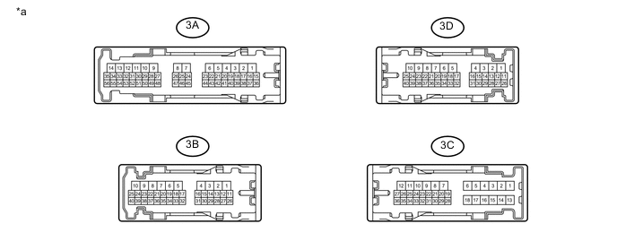
Text in Illustration *a Component without harness connected
(Instrument Panel Junction Block Assembly)
- - -
Front turn signal light
-
Measure the resistance according to the value(s) in the table below.
Standard Resistance for LH Tester Connection Condition Specified Condition 3A-20 - 3D-10 Always Below 1 Ω for RH Tester Connection Condition Specified Condition 3A-37 - 3D-5 Always Below 1 Ω Result Result Proceed to NG A OK B
-
-
Rear turn signal light
-
Measure the resistance according to the value(s) in the table below.
Standard Resistance for LH Tester Connection Condition Specified Condition 3A-20 - 3C-22 Always Below 1 Ω for RH Tester Connection Condition Specified Condition 3A-37 - 3C-19 Always Below 1 Ω Result Result Proceed to NG A OK B
-
-
Side turn signal light
-
Measure the resistance according to the value(s) in the table below.
Standard Resistance for LH Tester Connection Condition Specified Condition 3A-20 - 3A-40 Always Below 1 Ω for RH Tester Connection Condition Specified Condition 3A-37 - 3B-32 Always Below 1 Ω Result Result Proceed to NG A OK (w/o Reverse Shift-linked Mirror) B OK (for LH with Reverse Shift-linked Mirror) C OK (for RH with Reverse Shift-linked Mirror) D
-
A
REPLACE INSTRUMENT PANEL JUNCTION BLOCK ASSEMBLY Click here
B
REPLACE COMBINATION METER ASSEMBLY Click here
D
REPLACE OUTER MIRROR CONTROL ECU ASSEMBLY RH Click here
C
-
-
REPLACE OUTER MIRROR CONTROL ECU ASSEMBLY LH
-
Replace the outer mirror control ECU assembly LH with a new or known good one Click here.
-
Recheck for DTCs Click here.
Result Result Proceed to DTCs are not output. A DTCs are output. B
A
END
B
REPLACE COMBINATION METER ASSEMBLY Click here
-
-
REPLACE OUTER MIRROR CONTROL ECU ASSEMBLY RH
-
Replace the outer mirror control ECU assembly RH with a new or known good one Click here.
-
Recheck for DTCs Click here.
Result Result Proceed to DTCs are not output. A DTCs are output. B
A
END
B
REPLACE COMBINATION METER ASSEMBLY Click here
-