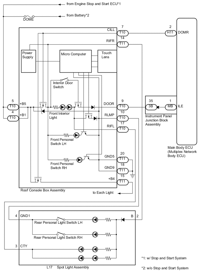
LIGHTING SYSTEM Interior Light Power Source Circuit
DESCRIPTION
The main body ECU (multiplex network body ECU) controls the solid-state relay, that is built into the roof console box assembly, to supply power to the interior lights.
WIRING DIAGRAM
CAUTION / NOTICE / HINT
Note
Inspect the fuses for circuits related to this system before performing the following inspection procedure.
PROCEDURE
-
INSPECT ROOF CONSOLE BOX ASSEMBLY
-
Remove the roof console box assembly Click here.
-
Inspect the roof console box assembly Click here.
OK Roof console box assembly is normal. Result Result Proceed to OK (w/o Stop and start system) A OK (w/ Stop and start system) B NG C
B 
CHECK HARNESS AND CONNECTOR (ENGINE STOP AND START ECU - ROOF CONSOLE BOX ASSEMBLY) Click here
C 
REPLACE ROOF CONSOLE BOX ASSEMBLY Click here
A 
-
-
CHECK HARNESS AND CONNECTOR (DOME FUSE - ROOF CONSOLE BOX ASSEMBLY)
-
Measure the voltage according to the value(s) in the table below.
Standard Voltage Tester Connection Condition Specified Condition T10-4 (+B1) - Body ground Engine switch off 11 to 14 V T10-5 (+B5) - Body ground Engine switch off 11 to 14 V
NG
REPAIR OR REPLACE HARNESS OR CONNECTOR
OK
-
-
CHECK HARNESS AND CONNECTOR (ROOF CONSOLE BOX ASSEMBLY - MAIN BODY ECU (MULTIPLEX NETWORK BODY ECU))
-
Disconnect the H11 main body ECU (multiplex network body ECU) connector.
-
Measure the resistance according to the value(s) in the table below.
Standard Resistance Tester Connection Condition Specified Condition T10-7 (CILL) - H11-2 (DOMR) Always Below 1 Ω T10-7 (CILL) - Body ground Always 10 kΩ or higher
OK
PROCEED TO NEXT SUSPECTED AREA SHOWN IN PROBLEM SYMPTOMS TABLE Click here
NG
REPAIR OR REPLACE HARNESS OR CONNECTOR
-
-
CHECK HARNESS AND CONNECTOR (ENGINE STOP AND START ECU - ROOF CONSOLE BOX ASSEMBLY)
-
Measure the voltage according to the value(s) in the table below.
Standard Voltage Tester Connection Condition Specified Condition T10-4 (+B1) - Body ground Engine switch on (IG) 10.5 to 16 V T10-5 (+B5) - Body ground Engine switch on (IG) 10.5 to 16 V
NG
GO TO STOP AND START SYSTEM Click here
OK
-
-
CHECK HARNESS AND CONNECTOR (ROOF CONSOLE BOX ASSEMBLY - MAIN BODY ECU (MULTIPLEX NETWORK BODY ECU))
-
Disconnect the H11 main body ECU (multiplex network body ECU) connector.
-
Measure the resistance according to the value(s) in the table below.
Standard Resistance Tester Connection Condition Specified Condition T10-7 (CILL) - H11-2 (DOMR) Always Below 1 Ω T10-7 (CILL) - Body ground Always 10 kΩ or higher
OK
PROCEED TO NEXT SUSPECTED AREA SHOWN IN PROBLEM SYMPTOMS TABLE Click here
NG
REPAIR OR REPLACE HARNESS OR CONNECTOR
-