THEFT DETERRENT SYSTEM TERMINALS OF ECU
-
CHECK MAIN BODY ECU (MULTIPLEX NETWORK BODY ECU) AND INSTRUMENT PANEL JUNCTION BLOCK ASSEMBLY
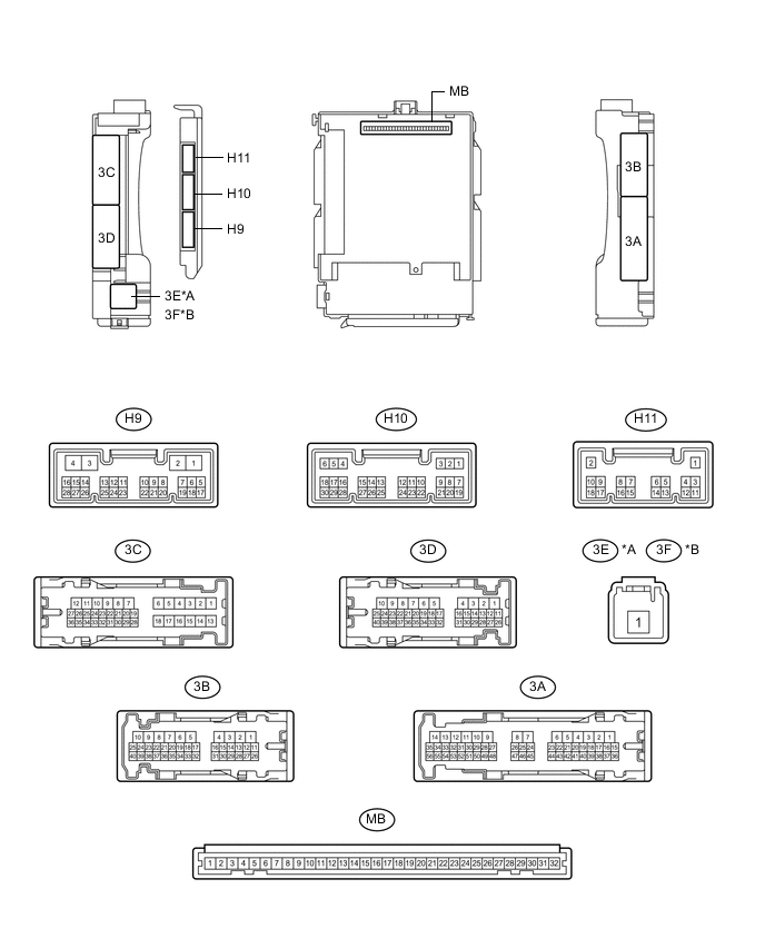
*A for LHD *B for RHD
-
Remove the main body ECU (multiplex network body ECU) from the instrument panel junction block assembly.
-
Reconnect the instrument panel junction block assembly connectors.
-
Measure the resistance and voltage according to the value(s) in the table below.
Tech Tips
Measure the values on the wire harness side with the connector disconnected.
Terminal No. (Symbol) Wiring Color Terminal Description Condition Specified Condition MB-30 (BECU) - Body ground - Battery power supply Always 11 to 14 V MB-31 (ALTB) - Body ground - Battery power supply Always 11 to 14 V MB-32 (IG) - Body ground - Ignition power supply (IG signal) Engine switch on (IG) → off 11 to 14 V → Below 1 V MB-29 (ACC) - Body ground - Ignition power supply (ACC signal) Engine switch on (ACC) → off 11 to 14 V → Below 1 V MB-11 (GND1) - Body ground - Ground Always Below 1 Ω H9-3 (GND2) - Body ground W-B - Body ground Ground Always Below 1 Ω MB-2 (FLCY) - Body ground - Front door courtesy light switch LH input Front door LH closed (OFF) → open (ON) 10 kΩ or higher → Below 1 Ω MB-4 (FRCY) - Body ground - Front door courtesy light switch RH input Front door RH closed (OFF) → open (ON) 10 kΩ or higher → Below 1 Ω H11-3 (LCTY) - Body ground G - Body ground Rear door courtesy light switch LH input Rear door LH closed (OFF) → open (ON) 10 kΩ or higher → Below 1 Ω H10-6 (RCTY) - Body ground B - Body ground Rear door courtesy light switch RH input Rear door RH closed (OFF) → open (ON) 10 kΩ or higher → Below 1 Ω H10-19 (LGCY) - Body ground GR - Body ground Luggage compartment door courtesy light switch input Luggage compartment door closed (OFF) → open (ON) 10 kΩ or higher → Below 1 Ω MB-20 (HCTY) - Body ground - Engine hood courtesy switch input Engine hood open (OFF) → closed (ON) 10 kΩ or higher → Below 1 Ω -
Install the main body ECU (multiplex network body ECU) to instrument panel junction block assembly.
-
Measure the voltage and check for pulses according to the value(s) in the table below.
Terminal No. (Symbol) Wiring Color Terminal Description Condition Specified Condition H10-7 (LSFL) - Body ground L - Body ground Front door LH unlock detection switch input Front door LH unlocked Below 1 V H10-7 (LSFL) - Body ground L - Body ground Front door LH unlock detection switch input Front door LH locked Pulse generation H10-18 (LSFR) - Body ground W - Body ground Front door RH unlock detection switch input Front door RH unlocked Below 1 V H10-18 (LSFR) - Body ground W - Body ground Front door RH unlock detection switch input Front door RH locked Pulse generation 3C-17 (LSR) - Body ground GR - Body ground Rear door LH unlock detection switch input Rear door LH or RH unlocked Below 1 V 3C-17 (LSR) - Body ground GR - Body ground Rear door LH unlock detection switch input Rear door LH and RH locked Pulse generation 3A-53 (LSR) - Body ground GR - Body ground Rear door RH unlock detection switch input Rear door RH or LH unlocked Below 1 V 3A-53 (LSR) - Body ground GR - Body ground Rear door RH unlock detection switch input Rear door RH and LH locked Pulse generation H9-8 (SSW1) - Body ground*1 LG - Body ground Intrusion sensor cancel switch signal Intrusion sensor cancel switch not pushed Pulse generation H9-8 (SSW1) - Body ground*1 LG - Body ground Intrusion sensor cancel switch signal Intrusion sensor cancel switch pushed Below 1 V H9-12 (ISIF) - Body ground*1 P - Body ground Intrusion sensor (theft warning ultrasonic sensor) signal input No moving object detected by sensor 11 to 14 V H9-12 (ISIF) - Body ground*1 P - Body ground Intrusion sensor (theft warning ultrasonic sensor) signal input Moving object detected by sensor during arming preparation state or armed state Below 1 V H9-18 (SSCL) - Body ground*1 B - Body ground Theft warning siren drive Theft warning siren sounding (Theft deterrent system in alarm sounding state) Pulse generation
(Below 1 V ← → 11 to 14 V)
3D-14 (SH) - Body ground*2 R - Body ground Security horn drive Security horn sounding
(Theft deterrent system is in alarm sounding state)
Pulse generation
(Below 1 V ← → 11 to 14 V)
3D-15 (HORN) - Body ground SB - Body ground Vehicle horn drive Vehicle horns sounding
(Theft deterrent system is in alarm sounding state)
Pulse generation
(Below 1 V ← → 11 to 14 V)
-
*1: w/ Intrusion Sensor Cancel Switch
-
*2: w/o Intrusion Sensor Cancel Switch
-
-